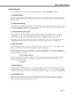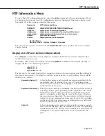
NTP Information Menu
Page 12-21
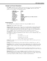
Display Local Server Information
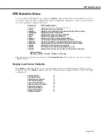
The
ntpinfo
command is used to display information about the local switch’s implementation
of
NTP
. To view local switch
NTP
information, enter the
ntpinfo
command at the system
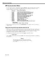
prompt. A screen similar to the following is shown:
system peer:
0.0.0.0
system peer mode:
unspec
leap indicator:
11
stratum:
16
precision:
-7
root distance:
0.00000 s
root dispersion:
0.00000 s
reference ID:
[0.0.0.0]
reference time:
00000000.00000000 Thu, Feb 7 1936 6:28:16.000
system flags:
monitor stats
frequency:
0.000 ppm
stability:
0.000 ppm
broadcastdelay:
0.003906 s
authdelay:
0.000122 s
Field Descriptions
The following section explains the fields shown using the
ntpinfo
command.
System peer.
The
IP
address of the switch.
System peer mode
. The peer mode of this remote association. There are five possible modes:
symmetric active, symmetric passive, client, server, and broadcast. The displayed mode is
assumed if this association becomes the switch’s host
NTP
server. For a description of the
modes, see
Display List of Peers the Server Knows About
on page 12-15. For a description of
how to configure a peer, see
Configuring a New Peer Association
on page 12-12.
Leap indicator
. The status of leap second insertion for this association. Leap seconds are
seconds that are added to the timestamp of an
NTP
entity to correct accumulated time errors.
The possible values are:
00
No warning.
01
Last minute has 61 seconds.
10
Last minute has 59 seconds.
11
Alarm condition (clock not synchronized)
Stratum
. The stratum level of the remote peer. If this number is
16
, the remote peer has not
been synchronized.
Precision
. The advertised precision of the switch. It will be a number between -4 and -20.
Root distance
. This is a signed fixed-point number indicating the total roundtrip delay to the
primary reference source at the root of the synchronization subnet, in seconds. Note that this
variable can take on both positive and negative values, depending on clock precision and
skew.
Rootdispersion
. This is a signed fixed-point number indicating the maximum error relative to
the primary reference source at the root of the synchronization subnet, in seconds. Only posi-
tive values are possible.
Reference ID
. This is a 32-bit code identifying the particular reference clock. In the case of
stratum 0 (unspecified) or stratum 1 (primary reference source), this is a four-octet, left-justi-
fied, zero-padded
ASCII
string. In the case of stratum 2 and greater (secondary reference) this
is the four-octet Internet address of the peer selected for synchronization.
Summary of Contents for Omni Switch/Router
Page 1: ...Part No 060166 10 Rev C March 2005 Omni Switch Router User Manual Release 4 5 www alcatel com ...
Page 4: ...page iv ...
Page 110: ...WAN Modules Page 3 40 ...
Page 156: ...UI Table Filtering Using Search and Filter Commands Page 4 46 ...
Page 164: ...Using ZMODEM Page 5 8 ...
Page 186: ...Displaying and Setting the Swap State Page 6 22 ...
Page 202: ...Creating a New File System Page 7 16 ...
Page 270: ...Displaying Secure Access Entries in the MPM Log Page 10 14 ...
Page 430: ...OmniChannel Page 15 16 ...
Page 496: ...Configuring Source Route to Transparent Bridging Page 17 48 ...
Page 542: ...Dissimilar LAN Switching Capabilities Page 18 46 ...
Page 646: ...Application Example DHCP Policies Page 20 30 ...
Page 660: ...GMAP Page 21 14 ...
Page 710: ...Viewing the Virtual Interface of Multicast VLANs Page 23 16 ...
Page 722: ...Application Example 5 Page 24 12 ...
Page 788: ...Viewing UDP Relay Statistics Page 26 24 ...
Page 872: ...The WAN Port Software Menu Page 28 46 ...
Page 960: ...Deleting a PPP Entity Page 30 22 ...
Page 978: ...Displaying Link Status Page 31 18 ...
Page 988: ...Displaying ISDN Configuration Entry Status Page 32 10 ...
Page 1024: ...Backup Services Commands Page 34 14 ...
Page 1062: ...Diagnostic Test Cable Schematics Page 36 24 ...
Page 1072: ...Configuring a Switch with an MPX Page A 10 ...
Page 1086: ...Page B 14 ...
Page 1100: ...Page I 14 Index ...

