Viewing Current Groups
Page 19-38
Viewing Current Groups
The
gp
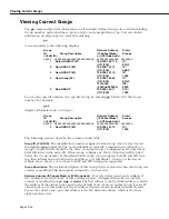
command provides information on all currently defined Groups in a switch including
Group number, network address, protocol type, and encapsulation type. You can obtain
information on all groups in a switch by entering:
gp
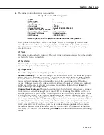
A screen similar to the following displays:
Group
Network Address
Proto/
ID
Group Description
(IP Subnet Mask)
Encaps
(:VLAN ID)
or (IPX Node Addr)
=====
===========================
=============== ========
1
Default GROUP (#1)
198.206.182.115
IP /
(ff.ff.ff.00)
ETH2
2
New GROUP (#2)
198.206.101.12
IP /
(ff.ff.ff.00)
SNAP
3
New GROUP (#3)
198.206.181.10
IP/
(ff.ff.ff.00)
1490
4
New Group (#4)
198.206.183.44
IP /
(ff.ff.ff.00)
ETH2
12314526
IPX /
(0020da:020484)
8023
5
New GROUP
198.206.143.11
CIP /
(ff.ff.ff.00)
1483
You can also get information on a specific Group by entering
gp
followed by the Group
number. For example,
gp 3
displays information just on Group 3:
Group
Network Address
Proto/
ID
Group Description
(IP Subnet Mask)
Encaps
(:VLAN ID)
or (IPX Node Addr)
=====
===========================
=============== ========
3
New GROUP (#3)
198.206.181.10
IP /
(ff.ff.ff.00)
1490
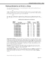
The following sections describe the columns in this table:
Group ID (:VLAN ID)
. The identification number assigned to this Group when it was created
through the
crgp
command. The Group identifier is typically consistent network-wide (i.e.,
Group 3 in this switch should be the same Group as Group 3 configured in all other Omni
Switch/Routers in the network). If this Group contains any
VLAN
s, then they will be listed
below the Group number. If the default VLAN in the Group supports both IP and IPX rout-
ing, then information on both (network address, etc) will display. Group 4 in the screen
sample above shows a case where both IP and IPX routing are supported.
Group Description
. The textual description of this Group that was entered when the Group was
created or modified. This description is limited to 30 characters.
Network Address (IP Subnet Mask) or (IPX Node Addr)
. For each virtual router port configured,
two addresses are listed. Both of these addresses were configured when the Group was
created or modified through
crgp
or
modvl
. The first address is the Network Address, which is
the address of the virtual router port for the default
VLAN
(
VLAN #1
) in this Group. For an IP
virtual router port, this address is the
IP
address, which is shown in dotted decimal format.
For an
IPX
virtual router port, this address is the
IPX
network address, which is shown as
eight hex characters.
Summary of Contents for Omni Switch/Router
Page 1: ...Part No 060166 10 Rev C March 2005 Omni Switch Router User Manual Release 4 5 www alcatel com ...
Page 4: ...page iv ...
Page 110: ...WAN Modules Page 3 40 ...
Page 156: ...UI Table Filtering Using Search and Filter Commands Page 4 46 ...
Page 164: ...Using ZMODEM Page 5 8 ...
Page 186: ...Displaying and Setting the Swap State Page 6 22 ...
Page 202: ...Creating a New File System Page 7 16 ...
Page 270: ...Displaying Secure Access Entries in the MPM Log Page 10 14 ...
Page 430: ...OmniChannel Page 15 16 ...
Page 496: ...Configuring Source Route to Transparent Bridging Page 17 48 ...
Page 542: ...Dissimilar LAN Switching Capabilities Page 18 46 ...
Page 646: ...Application Example DHCP Policies Page 20 30 ...
Page 660: ...GMAP Page 21 14 ...
Page 710: ...Viewing the Virtual Interface of Multicast VLANs Page 23 16 ...
Page 722: ...Application Example 5 Page 24 12 ...
Page 788: ...Viewing UDP Relay Statistics Page 26 24 ...
Page 872: ...The WAN Port Software Menu Page 28 46 ...
Page 960: ...Deleting a PPP Entity Page 30 22 ...
Page 978: ...Displaying Link Status Page 31 18 ...
Page 988: ...Displaying ISDN Configuration Entry Status Page 32 10 ...
Page 1024: ...Backup Services Commands Page 34 14 ...
Page 1062: ...Diagnostic Test Cable Schematics Page 36 24 ...
Page 1072: ...Configuring a Switch with an MPX Page A 10 ...
Page 1086: ...Page B 14 ...
Page 1100: ...Page I 14 Index ...

