Configuring Fast Spanning Tree
Page 17-34
Configuring Fast Spanning Tree
The Fast Spanning Tree (Rapid Reconfiguration) feature is designed to help provide an
802.1D standards-based method of quick recovery in the event of link, port and device
failures in an Ethernet local area network. By automatically identifying and utilizing
alternative secondary links, Fast Spanning Tree can rapidly converge backup connections
between network devices within as little as 1 second. In addition, new Spanning Tree
information can be processed faster.
If packets are broadcast to all ports (or flooded) in an attempt to deliver the data, networks
with physical loops will rebroadcast packets repeatedly and cause a network to become
severely congested. This congestion will adversely affect network performance.
While Spanning Tree prevents broadcast storms by blocking ports in the physical topology
that could result in flooded traffic being looped, Fast Spanning Tree minimizes downtime by
bringing these blocked secondary links into Forwarding mode as quickly as possible. If the
Root Port is lost, an Alternate Port on the Bridge can be made the new Root Port, and placed
into a Forwarding state immediately. The prior Root Port switches to a Listening state if it
becomes a Designated Port; otherwise, it enters a Blocking state.
Similarly, any Designated Port on the Bridge can be made the new Root Port, and placed into
a Forwarding state immediately. In this event, the existing (prior) Root Port changes to a
Designated Port role, without a corresponding gain or loss of connectivity. A Backup Port can
also be made the new Root Port and placed into Forwarding mode, resulting in the
Designated Port assuming a Listening state.
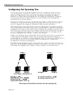
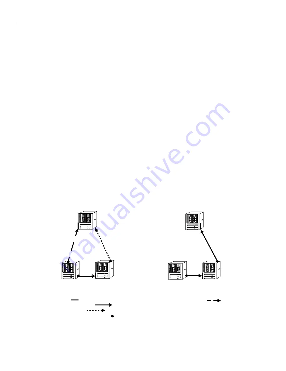
The following diagram illustrates how a typical network connection can fail, such as the A-C
Link shown below. Rapid Reconfiguration brings a blocked link - such as the B-C Link - into
Forwarding state, helping achieve quick recovery from failure of networked devices.
Recovering from Linked Device Failure with Fast Spanning Tree
Bridge C
Bridge B
Bridge A
A-C Link that will Fail =
Designated Bridge for Link =
Spanning Tree Link =
Redundant Link =
Root Port =
Bridge C
Bridge B
Bridge A
B-C becomes Root Port for C
(Backup Root 1)
(Root Bridge)
Summary of Contents for Omni Switch/Router
Page 1: ...Part No 060166 10 Rev C March 2005 Omni Switch Router User Manual Release 4 5 www alcatel com ...
Page 4: ...page iv ...
Page 110: ...WAN Modules Page 3 40 ...
Page 156: ...UI Table Filtering Using Search and Filter Commands Page 4 46 ...
Page 164: ...Using ZMODEM Page 5 8 ...
Page 186: ...Displaying and Setting the Swap State Page 6 22 ...
Page 202: ...Creating a New File System Page 7 16 ...
Page 270: ...Displaying Secure Access Entries in the MPM Log Page 10 14 ...
Page 430: ...OmniChannel Page 15 16 ...
Page 496: ...Configuring Source Route to Transparent Bridging Page 17 48 ...
Page 542: ...Dissimilar LAN Switching Capabilities Page 18 46 ...
Page 646: ...Application Example DHCP Policies Page 20 30 ...
Page 660: ...GMAP Page 21 14 ...
Page 710: ...Viewing the Virtual Interface of Multicast VLANs Page 23 16 ...
Page 722: ...Application Example 5 Page 24 12 ...
Page 788: ...Viewing UDP Relay Statistics Page 26 24 ...
Page 872: ...The WAN Port Software Menu Page 28 46 ...
Page 960: ...Deleting a PPP Entity Page 30 22 ...
Page 978: ...Displaying Link Status Page 31 18 ...
Page 988: ...Displaying ISDN Configuration Entry Status Page 32 10 ...
Page 1024: ...Backup Services Commands Page 34 14 ...
Page 1062: ...Diagnostic Test Cable Schematics Page 36 24 ...
Page 1072: ...Configuring a Switch with an MPX Page A 10 ...
Page 1086: ...Page B 14 ...
Page 1100: ...Page I 14 Index ...

