Gantry
3-6
CardioMD Service Manual
1MAN0158-H11 04-2005 CSIP Level 1
Linear Motion
Controller
(Y and X Axes)
Rotate Motion
Controller
(Rotate and Table)
Y Drive Motor
Amplifier
Rotate Drive Motor
Amplifier
X Dr
iv
e
Mot
o
r
Am
pli
fie
r
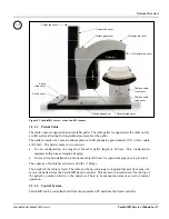
Figure 3.5 Electronics behind front cover
Safety Board
I
0
100V 120V 200V 220V 240V
12A 12A 6.25A 6.25A 6.25A
FUSE
FUSE
MAINS VOLTAGE
SETTING
FUSE RATING
( both fuses )
Secondary fuses
10A both
Figure 3.6 Electronics behind rear cover
3.2.1
AC Power Supply
The gantry power supply is located in the lower left corner in the rear of the table console. It
powers the entire system except for the processing station. The outputs are divided into two
groups:
•
One group of continuous outputs (see Table 3.1 on page 3-7)
•
One group of safety interrupted outputs (see Table 3.2 on page 3-7).
All low voltage outputs are protected by PTC fuses.
Note
. To reset the PTC fuses, all loads on the affected output must be removed; power must be
removed momentarily and then reapplied. Any capacitance within the circuitry will cause the fuse
not to reset. These fuses are not accessible and are not field-replaceable. Should one of these fuses
fail, the entire power supply must be replaced.
Summary of Contents for CARDIOMD
Page 1: ...CARDIOMD SERVICE MANUAL 1MAN0158 H11 04 2005 CSIP Level 1 ...
Page 10: ...Introduction x CardioMD Service Manual 1MAN0158 H11 04 2005 CSIP Level 1 ...
Page 16: ...Safe Operating Practices 1 6 CardioMD Service Manual 1MAN0158 H11 04 2005 CSIP Level 1 ...
Page 164: ...Detector Calibration Files 5 60 CardioMD Service Manual 1MAN0158 H11 04 2005 CSIP Level 1 ...
Page 328: ...Installation Procedures 9 38 CardioMD Service Manual 1MAN0158 H11 04 2005 CSIP Level 1 ...
Page 348: ...Planned Maintenance Procedures 11 6 CardioMD Service Manual 1MAN0158 H11 04 2005 CSIP Level 1 ...
Page 465: ......


