Installation
8-56
CardioMD Service Manual
1MAN0158-H11 04-2005 CSIP Level 1
29.
Mount the LED box using four M6 screws
from underneath the top plate.
The photo on the right shows the assembled
and mounted wall-mount PC stand.
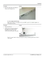
The next step consists in mounting wiremolds and routing cables. Proceed as follows:
Procedure Details
1.
Route wiremolds nicely from the wall-
mount to the gantry.
Use the adhesive on the wiremolds to
attach them to the wall.
The wiremolds provided with the system
include angles and turns needed for most
installations.
In case you need additional parts, these can be
obtained locally.
Note
. The adhesive on the wiremolds is only intended as an aid when installing. The adhesive is
not sufficiently strong to keep wiremolds in place for longer periods of time.
Summary of Contents for CARDIOMD
Page 1: ...CARDIOMD SERVICE MANUAL 1MAN0158 H11 04 2005 CSIP Level 1 ...
Page 10: ...Introduction x CardioMD Service Manual 1MAN0158 H11 04 2005 CSIP Level 1 ...
Page 16: ...Safe Operating Practices 1 6 CardioMD Service Manual 1MAN0158 H11 04 2005 CSIP Level 1 ...
Page 164: ...Detector Calibration Files 5 60 CardioMD Service Manual 1MAN0158 H11 04 2005 CSIP Level 1 ...
Page 328: ...Installation Procedures 9 38 CardioMD Service Manual 1MAN0158 H11 04 2005 CSIP Level 1 ...
Page 348: ...Planned Maintenance Procedures 11 6 CardioMD Service Manual 1MAN0158 H11 04 2005 CSIP Level 1 ...
Page 465: ......


