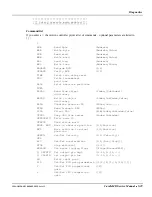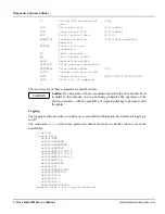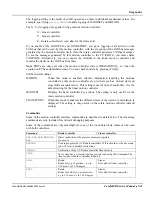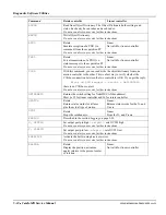
Diagnostics
1MAN0158-H11 04-2005 CSIP Level 1
CardioMD Service Manual
5-17
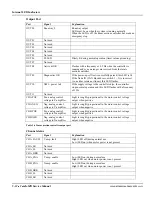
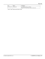
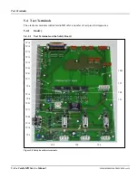
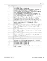
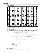
+15V, +5V,
–5V, –15V,
+13V
are DC test points for the low voltages used in the detector. The readings should
be within 5% of these values.
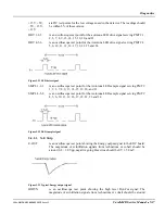
DRV 1-2-3
is an oscilloscope test point for the autotune LED drive signal serving PMT # 1,
2, 3, 7, 8, 9, 13, 14, 15, 19, 20, and 21.
DRV 4-5-6
is an oscilloscope test point for the Autotune LED drive signal serving PMT # 4,
5, 6, 10, 11, 12, 16, 17, 18, 22, 23 and 24.
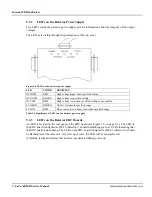
Figure 5.11 LED drive signal
SMPL 1-2-3
is an oscilloscope test point for the Autotune LED sample signal serving PMT #
1, 2, 3, 7, 8, 9, 13, 14, 15, 19, 20, and 21.
SMPL 4-5-6
is an oscilloscope test point for the Autotune LED sample signal serving PMT #
4, 5, 6, 10, 11, 12, 16, 17, 18, 22, 23 and 24.
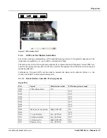
Figure 5.12 LED sample signal
5.4.2.3
X–E Strip
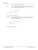
E-OUT
is an oscilloscope test point showing the Energy output signal to the EDC board.
The magnitude of scintillation signals from technetium or cobalt should be
around 0.8 – 1.0 Vpp, negative going. Base line should be 0 V
±
50 mV.
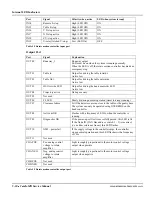
Figure 5.13 Typical Energy output signal
HIDYN
is an oscilloscope test point showing the high level DynCor signal. The
magnitude of scintillation signals from technetium or cobalt should be around
Summary of Contents for CARDIOMD
Page 1: ...CARDIOMD SERVICE MANUAL 1MAN0158 H11 04 2005 CSIP Level 1 ...
Page 10: ...Introduction x CardioMD Service Manual 1MAN0158 H11 04 2005 CSIP Level 1 ...
Page 16: ...Safe Operating Practices 1 6 CardioMD Service Manual 1MAN0158 H11 04 2005 CSIP Level 1 ...
Page 164: ...Detector Calibration Files 5 60 CardioMD Service Manual 1MAN0158 H11 04 2005 CSIP Level 1 ...
Page 328: ...Installation Procedures 9 38 CardioMD Service Manual 1MAN0158 H11 04 2005 CSIP Level 1 ...
Page 348: ...Planned Maintenance Procedures 11 6 CardioMD Service Manual 1MAN0158 H11 04 2005 CSIP Level 1 ...
Page 465: ......


