Detector Repairs
6-12
CardioMD Service Manual
1MAN0158-H11 04-2005 CSIP Level 1
6.3.7
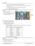
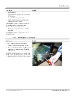
Replacing the Collimator ID Cable
Procedure Details
The collimator ID cable connects the detector
contact board that engages the collimator to
the EDC module. To change this cable the
detector must be disassembled to the same
level as for changing PMT’s.
1.
Follow the procedure to this stage as
described in section 0 on page 6-7.
2.
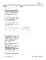
Remove the collimator support cover by
unscrewing the 4 cover screws in the plate
next to the collimator.
3.
Disconnect the cable from the detector
contact board and from the EDC module.
4.
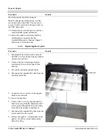
The cable’s exit hole in the detector
casting is sealed with black RTV. Use a
knife to remove the old seal and replace
the cable.
5.
Connect the cable to the detector contact
board and seal the exit hole once again
with black RTV.
6.
Route the cable to the EDC module and
re-assemble the detector.
6.3.8
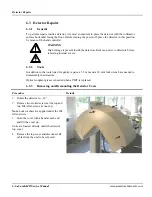
Aligning Collision Sensors on the Detector Cover
Procedure Details
1.
Remove the detector cover as described in
section 6.3.3 on page 6-6.
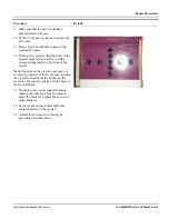
The collision sensors for the detector cover are
located where the two M4 Allen screws were
removed.
2.
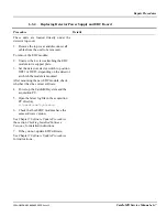
Unplug the cables from the collision
sensors and turn the sensors
counterclockwise to loosen them. Remove
the sensors.
3.
Make sure that the M3 bracket alignment
screw is in place.
Summary of Contents for CARDIOMD
Page 1: ...CARDIOMD SERVICE MANUAL 1MAN0158 H11 04 2005 CSIP Level 1 ...
Page 10: ...Introduction x CardioMD Service Manual 1MAN0158 H11 04 2005 CSIP Level 1 ...
Page 16: ...Safe Operating Practices 1 6 CardioMD Service Manual 1MAN0158 H11 04 2005 CSIP Level 1 ...
Page 164: ...Detector Calibration Files 5 60 CardioMD Service Manual 1MAN0158 H11 04 2005 CSIP Level 1 ...
Page 328: ...Installation Procedures 9 38 CardioMD Service Manual 1MAN0158 H11 04 2005 CSIP Level 1 ...
Page 348: ...Planned Maintenance Procedures 11 6 CardioMD Service Manual 1MAN0158 H11 04 2005 CSIP Level 1 ...
Page 465: ......

