Detectors
3-24
CardioMD Service Manual
1MAN0158-H11 04-2005 CSIP Level 1
3.3
Detectors
3.3.1
General
The CardioMD detectors are based on a unique technology that provides superior performance in
a rather simple design. The photomultipliers – PMT’s – employed are 3” square; a total of 24
PMT’s are arranged in a 6
×
4 rectangular pattern in each detector. Each PMT has an integrated
preamplifier and automatic gain stabilization based on a built-in LED.
Position and energy information is summed and preprocessed in an analog circuitry directly on the
outputs from the PMT’s. From that circuitry, the information is passed on to a group of A/D
converters and, from here on, all processing is digital. The output from the detector is fully
corrected, digital image data transferred event by event on a serial interface. The serial interface
employed is IEEE 1394 FireWire.
The entire detector is powered from 55 V DC. A power supply inside the detector provides supply
voltages for the analog circuitry and a negative high voltage for the PMT’s.
3.3.2
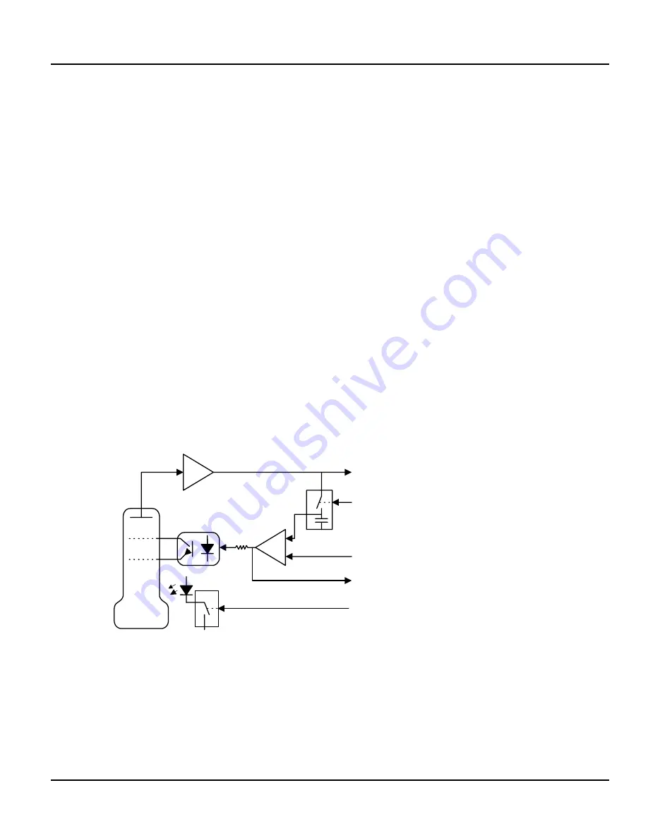
Automatic PMT Gain Control – Autotune
For gain control of the individual PMT’s, a light reference (LED) is built into each PMT. This
LED flashes for 3 µsec every 10 msec, and the response from the PMT is sampled and compared
to a reference voltage. The output from the comparator is fed into a gain control circuit on the
PMT. In this way a closed loop ensures that the response from the reference light (the LED)
always corresponds to the reference voltage. The reference voltage is set up from a DAC that is
dedicated for each PMT. The individual PMT gain settings can now be digitally controlled.
The output from the comparator is also used as information about the gain margin of the PMT
(working point).
OUT
SAMPLE
TUNE REF.
VOLTAGE
WORKING
POINT
LED DRIVE
Figure 3.19 Auto tune circuit
3.3.3
Dynamic Linearity Correction – DynCor
DynCor provides a non-linear relationship between the group sum and the position of the
scintillations. This non-linearity compensates for a distortion in the photon optics between the
crystal and the PMT’s.
Summary of Contents for CARDIOMD
Page 1: ...CARDIOMD SERVICE MANUAL 1MAN0158 H11 04 2005 CSIP Level 1 ...
Page 10: ...Introduction x CardioMD Service Manual 1MAN0158 H11 04 2005 CSIP Level 1 ...
Page 16: ...Safe Operating Practices 1 6 CardioMD Service Manual 1MAN0158 H11 04 2005 CSIP Level 1 ...
Page 164: ...Detector Calibration Files 5 60 CardioMD Service Manual 1MAN0158 H11 04 2005 CSIP Level 1 ...
Page 328: ...Installation Procedures 9 38 CardioMD Service Manual 1MAN0158 H11 04 2005 CSIP Level 1 ...
Page 348: ...Planned Maintenance Procedures 11 6 CardioMD Service Manual 1MAN0158 H11 04 2005 CSIP Level 1 ...
Page 465: ......


