External LED Indicators
5-4
CardioMD Service Manual
1MAN0158-H11 04-2005 CSIP Level 1
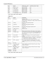
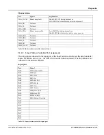
During normal operation, only the green MOTOR POWER LED is ON.
The yellow COLLISION LED is lit when the safety circuit is currently registering an impact on
one of the collision pads/covers. When this is the case, motions are only possible when the hand
controller Collision Override button is pressed. When the impact is removed, the Collision
Override button clears the collision state.
The green MOTOR POWER LED must be lit before any motion can take place. If this LED is off,
and neither of the adjacent yellow LED’s is on, there are 3 possible causes:
•
The hand controller Stop button has been pressed.
In that case, press the Collision Override button.
•
A Runaway signal can be issued by either motion controller. The two motion controllers are
constantly supervising each other. A missing response from one motion controller makes the
other issue a Runaway signal.
If this is the case, the red RUNAWAY LED on the safety board is lit. Try resetting both
motion controllers or rebooting the system.
•
The rotate, X or Y motion has exceeded the software-controlled end-stop and reached an
ultimate limit.
If that is the case, the red ULT_STOP LED on the safety board is lit and one or more of the
green LED’s labeled ULTIM. LIM is off (see Figure 5.5 on page 5-6). In this case, proceed as
follows:
1.
Set the ULT_STOP OVERRIDE switch on the safety board in position ON (down).
2.
Press the hand controller Collision Override button and the relevant motion button to back
away from the end stop.
3.
Press the ULT_STOP RESET button on the safety board once to reset the stop relay – the red
LED should turn off.
4.
Set the ULT_STOP OVERRIDE switch back to position OFF (upwards).
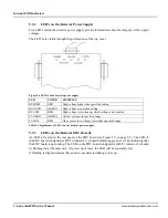
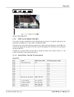
The system has a second green LED indicating the status of the system’s 115 V AC power output.
In Series III systems, this LED is placed on the connector panel at the rear of the table base and
indicates the status of the acquisition PC and ECG gate power supply.
Figure 5.3 LED indicating status of 115 V output power (CardioMD Series III)
On Series I and II systems, the LED is placed in the lower part of the side panel and indicates the
status of the acquisition PC power supply.
III
I, II
Summary of Contents for CARDIOMD
Page 1: ...CARDIOMD SERVICE MANUAL 1MAN0158 H11 04 2005 CSIP Level 1 ...
Page 10: ...Introduction x CardioMD Service Manual 1MAN0158 H11 04 2005 CSIP Level 1 ...
Page 16: ...Safe Operating Practices 1 6 CardioMD Service Manual 1MAN0158 H11 04 2005 CSIP Level 1 ...
Page 164: ...Detector Calibration Files 5 60 CardioMD Service Manual 1MAN0158 H11 04 2005 CSIP Level 1 ...
Page 328: ...Installation Procedures 9 38 CardioMD Service Manual 1MAN0158 H11 04 2005 CSIP Level 1 ...
Page 348: ...Planned Maintenance Procedures 11 6 CardioMD Service Manual 1MAN0158 H11 04 2005 CSIP Level 1 ...
Page 465: ......


