Diagnostics
1MAN0158-H11 04-2005 CSIP Level 1
CardioMD Service Manual
5-15
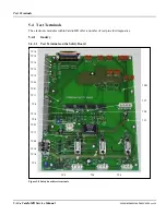
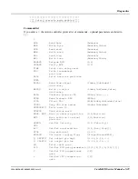
Test Terminal
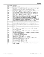
Description
TP1
+24 V DC power input
TP2
Return (reference) for the +24 V DC power input
TP3
+24 V DC if vertical and horizontal ultimate stop switches are OK and if multifuse MP3
on the safety board is not blown. Otherwise the voltage reading is 0 V DC
TP4
+24 V DC if rotational ultimate stop switches are OK and if multifuse MP3 on the safety
board is not blown. Otherwise the voltage reading is 0 V DC
TP5
+24 V DC if multifuse MP3 is OK. If the fuse is blown, the voltage reading is 0 V DC
TP6
+24 V DC if the table (gantry) E-Stop is not engaged and multifuse MP4 on the safety
board is not blown. Otherwise the voltage reading is 0 V DC
TP7
+24 V DC if the remote E-Stop (next to the acquisition PC) is not engaged and multifuse
MP4 on the safety board is not blown. Otherwise the voltage reading is 0 V DC
TP8
+24 V DC if the collision circuit (pads or covers) is not detecting a collision and
multifuse MP2 on the safety board is not blown. Otherwise the voltage reading is 0 V DC
TP9
+24 V DC during normal operation. Signal goes to approx. 0 V DC when one of the stop
buttons is pressed (E-Stop or hand controller Stop). After activation of the hand
controller Collision Override button, the signal once again goes to +24 V DC
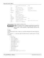
TP10
Not to be used by Service
TP11
Status of table position switch. A transition from 0 to +4 V DC or from +4 to 0 V DC
indicates that the table is passing its center position as used for patient load positioning
TP12
0 V DC. If +12 to 16 V DC is measured, the master motion controller has issued a
Runaway fault
TP13
0 V DC. If +12 to 16 V DC is measured, the slave motion controller has issued a
Runaway fault
TP14
Approx. 0 V DC indicates that the table is moving inwards. +24 V DC indicates that the
table is not moving inwards
TP15
Approx. 0 V DC indicates that the table is moving outwards. +24 V DC indicates that the
table is not moving outwards
TP16
Hand controller LED drive signal. If +24 V DC the hand controller LED is off. If approx.
0 V DC the hand controller LED is on
TP17
+ 5 V DC. Internally generated and used voltage
TP18
Return (reference) for TP19 and TP 20
TP19
Motion cont 5 V used internally on the safety board
TP20
Master motion controller burst clock output to read positions from the three absolute
encoders. Signal transition between approx. 0 and +5 V
TP21
Return (reference) for the +24 V DC power input
TP22
Return (reference) for the +24 V DC power input
TP23
Return (reference) for the +24 V DC power input
TP24
0 V DC during normal operation. If +12 to 16 V DC, one of the motion controllers has
issued a Runway fault
Summary of Contents for CARDIOMD
Page 1: ...CARDIOMD SERVICE MANUAL 1MAN0158 H11 04 2005 CSIP Level 1 ...
Page 10: ...Introduction x CardioMD Service Manual 1MAN0158 H11 04 2005 CSIP Level 1 ...
Page 16: ...Safe Operating Practices 1 6 CardioMD Service Manual 1MAN0158 H11 04 2005 CSIP Level 1 ...
Page 164: ...Detector Calibration Files 5 60 CardioMD Service Manual 1MAN0158 H11 04 2005 CSIP Level 1 ...
Page 328: ...Installation Procedures 9 38 CardioMD Service Manual 1MAN0158 H11 04 2005 CSIP Level 1 ...
Page 348: ...Planned Maintenance Procedures 11 6 CardioMD Service Manual 1MAN0158 H11 04 2005 CSIP Level 1 ...
Page 465: ......


