Installation
1MAN0158-H11 04-2005 CSIP Level 1
CardioMD Service Manual
8-73
8.3.3.31
Protecting Power and Ethernet Cables on the Floor
Procedure Details
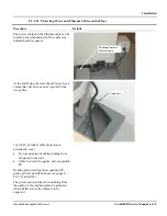
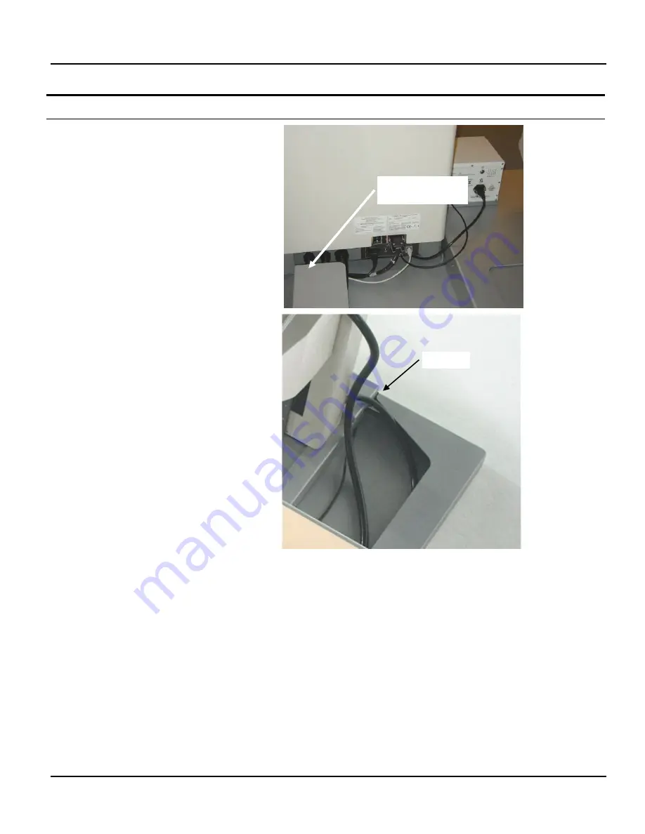
The power cable and the Ethernet cable can be
routed in the left-hand side of the cable tray
behind the table console.
At the end facing the wall, the cable tray has a
cutout that will serve as an exit point for the
two cables.
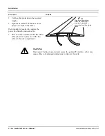
3 m (10 ft) of rubber cable protectors is
provided to cover:
•
Power and network cables running from
the gantry to the wall
•
Cable between the gantry and acquisition
PC.
Routing and protecting the acquisition PC-
gantry cable is described above (see page 8-
46, 8-57 and 8-63).
The power and network cables running from
the gantry to the wall must also be protected
where traffic across the cables is to be
expected.
Routing power and
Ethernet cable
Cable exit
Summary of Contents for CARDIOMD
Page 1: ...CARDIOMD SERVICE MANUAL 1MAN0158 H11 04 2005 CSIP Level 1 ...
Page 10: ...Introduction x CardioMD Service Manual 1MAN0158 H11 04 2005 CSIP Level 1 ...
Page 16: ...Safe Operating Practices 1 6 CardioMD Service Manual 1MAN0158 H11 04 2005 CSIP Level 1 ...
Page 164: ...Detector Calibration Files 5 60 CardioMD Service Manual 1MAN0158 H11 04 2005 CSIP Level 1 ...
Page 328: ...Installation Procedures 9 38 CardioMD Service Manual 1MAN0158 H11 04 2005 CSIP Level 1 ...
Page 348: ...Planned Maintenance Procedures 11 6 CardioMD Service Manual 1MAN0158 H11 04 2005 CSIP Level 1 ...
Page 465: ......


