Diagnostics
1MAN0158-H11 04-2005 CSIP Level 1
CardioMD Service Manual
5-3
5.1
Introduction
Diagnostics follow a four-layer scheme:
1.
External LED’s accessible to operator and service personnel.
2.
Internal LED’s on electronic modules.
3.
Internal electrical test points on modules.
4.
Software diagnostics via RS-232 interface to motion controllers and EDC modules and log
files on the acquisition PC.
5.2
External LED Indicators
CardioMD offers a number of LED’s that are visible from the outside. These LED’s are described
in the following sections.
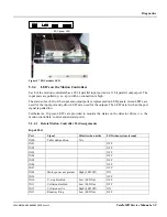
The system has three LED’s indicating the status of the safety circuit.
On Series III systems, these LED’s are placed in a panel on the acquisition PC stand.
Figure 5.1 COLLISION, MOTOR POWER and E-STOP status LED’s (CardioMD Series III)
On Series I and II systems, the LED’s are located in the upper part of the connector panel on the
side of the table console.
Figure 5.2 COLLISION, MOTOR POWER and E-STOP status LED’s (CardioMD Series I and II)
III
I, II
Summary of Contents for CARDIOMD
Page 1: ...CARDIOMD SERVICE MANUAL 1MAN0158 H11 04 2005 CSIP Level 1 ...
Page 10: ...Introduction x CardioMD Service Manual 1MAN0158 H11 04 2005 CSIP Level 1 ...
Page 16: ...Safe Operating Practices 1 6 CardioMD Service Manual 1MAN0158 H11 04 2005 CSIP Level 1 ...
Page 164: ...Detector Calibration Files 5 60 CardioMD Service Manual 1MAN0158 H11 04 2005 CSIP Level 1 ...
Page 328: ...Installation Procedures 9 38 CardioMD Service Manual 1MAN0158 H11 04 2005 CSIP Level 1 ...
Page 348: ...Planned Maintenance Procedures 11 6 CardioMD Service Manual 1MAN0158 H11 04 2005 CSIP Level 1 ...
Page 465: ......


