Diagnostics
1MAN0158-H11 04-2005 CSIP Level 1
CardioMD Service Manual
5-43
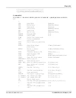
The error codes are bitmapped individually for each axis. The 0x01 bit is the encoder position
discrepancy. Thus the message above indicates a runaway being caused by an encoder error in the
Z-axis (rotate).
Following a runaway error, each axis will assert the 0x02 bit because motor power is lost
(removed by the safety board via the motion controller(s)). As the axes are not scanned
simultaneously, these bits will occur in an arbitrary sequence and may cause multiple entries in
the log file. An example is given below:
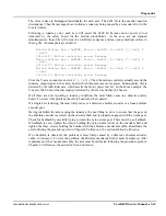
Motion Status: Ack = 0xFFFF, Error = 0x0010, X = 0x00, Y = 0x01, Z
= 0x00
[21.18.17] Motion controller error: Runaway
Motion Status: Ack = 0xFFFF, Error = 0x8011, X = 0x00, Y = 0x03, Z
= 0x02
[21.18.17] Motion controller error: Runaway
Motion Status: Ack = 0xFFFF, Error = 0x8011, X = 0x02, Y = 0x03, Z
= 0x02
[21.18.17] Motion controller error: Runaway
First, the Y-axis encounters an error (
Y = 0x01
). Then the motion controller actually asserts the
runaway output signal to the safety board, which then removes motor power. Subsequently, this is
detected by the individual axis, which asserts the motor power lost bit. In the above example, the
Y-axis is first to show the discrepancy followed by the Z-axis and then the X-axis.
If all three axes are reporting a runaway condition, the most likely cause is a defective safety
board. To correct this problem, the safety board must be replaced.
If a single axis is failing, the most likely cause is a defective absolute encoder or a loose absolute
encoder gear.
Having identified the axis causing the runaway, the next thing to do is to ensure that the gear on
the absolute encoder is secured on the encoder shaft and is properly engaged with the worm gear.
Check for backlash by carefully trying to rotate the nylon worm gear. There must be
no
backlash.
If backlash is seen, tighten the screws holding the nylon worm wheel on the encoder shaft, and
tighten the three screws holding the bracket with the absolute encoder assembly. Recalibrate the
axis following the procedure given in Chapter 4
Calibration
, the section
Motion Calibration
.
If no backlash is observed, the problem is most likely caused by a defective absolute encoder,
cable, or connector. To solve the problem, the absolute encoder and cable must be replaced. After
replacement of the encoder and cable, the axis must be calibrated following the procedure given in
Chapter 4
Calibration
, the section
Motion Calibration
.
Summary of Contents for CARDIOMD
Page 1: ...CARDIOMD SERVICE MANUAL 1MAN0158 H11 04 2005 CSIP Level 1 ...
Page 10: ...Introduction x CardioMD Service Manual 1MAN0158 H11 04 2005 CSIP Level 1 ...
Page 16: ...Safe Operating Practices 1 6 CardioMD Service Manual 1MAN0158 H11 04 2005 CSIP Level 1 ...
Page 164: ...Detector Calibration Files 5 60 CardioMD Service Manual 1MAN0158 H11 04 2005 CSIP Level 1 ...
Page 328: ...Installation Procedures 9 38 CardioMD Service Manual 1MAN0158 H11 04 2005 CSIP Level 1 ...
Page 348: ...Planned Maintenance Procedures 11 6 CardioMD Service Manual 1MAN0158 H11 04 2005 CSIP Level 1 ...
Page 465: ......

