System Components
2-6
CardioMD Service Manual
1MAN0158-H11 04-2005 CSIP Level 1
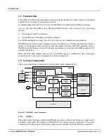
The acquisition PC interfaces to the gantry via a standard IEEE 1394 FireWire control interface.
The FireWire interface is used for all communication between the CardioMD gantry and the
acquisition PC, including the transmission of acquisition data to the PC.
For all detector motions, relative position feedback is provided by an incremental encoder
(relative encoder). On the rotate and vertical detector axes, the incremental encoder is
implemented by a resolver that is an integral part of the motor. The resolver output is converted to
an incremental signal by the motor amplifier. On the horizontal detector axis, an incremental
encoder is mounted on the motor shaft (as an integral part of the motor).
For absolute position information, the rotate, X and Y axes have absolute encoders. The absolute
encoders are used for position calibration after gantry power-up to index the relative encoders to a
known position. After this, the motion controllers simply look at the relative encoders for position
feedback but compare their outputs to the absolute encoders for verification. As long as the two
encoders for each motion (excluding the table) are in agreement as to the position, the motion
controllers are “happy”. If the positions deviate too much, all motions are halted (motor power is
removed).
The table axis has a simple position indicator switch which changes state when the mid-position is
reached. This is used to place the table at center position when the system moves to the patient
load position.
Motions are controlled by two dual-axis motion controllers (CANbus controllers) coupled in a
master-slave arrangement using a high speed synchronous communication link between the two.
The acquisition PC communicates only with the master controller. When the master controller
receives a motion command, it calculates the trajectory of the detectors and the instantaneous
velocity for each of the three axes (rotate, X, and Y). It controls the rotate axis directly and
transmits X and Y motion commands to the slave controller, which controls the X and Y detector
movements.
2.2.1.5
Power Supply
Power to the entire system is applied to the AC mains input on the gantry. The CardioMD has a
maximum power consumption of 1800 VA (including the power consumption of the acquisition
PC), which allows the CardioMD to be powered from a standard AC mains supply outlet.
Note
. Because the acquisition PC is powered from the gantry, the PC should be shut down
properly before gantry power is removed.
2.2.1.6
Emergency Stop Buttons
The CardioMD system has two Emergency Stop buttons, one located on the side of the table
console and one located next to the acquisition PC. The purpose of the E-Stop buttons is to stop
and disable all motions. Pressing the E-Stop causes motions to cease.
When the Emergency Stop button is released (and power to the rest of the system has not been
interrupted), the hand controlled motion is enabled but an interrupted SPECT acquisition will
remain stopped until restarted or resumed by the operator. The Emergency Stop button is released
by rotating the button clockwise.
2.2.1.7
Collision Sensing System
The CardioMD system is provided with collision sensors:
•
On the collimators
Summary of Contents for CARDIOMD
Page 1: ...CARDIOMD SERVICE MANUAL 1MAN0158 H11 04 2005 CSIP Level 1 ...
Page 10: ...Introduction x CardioMD Service Manual 1MAN0158 H11 04 2005 CSIP Level 1 ...
Page 16: ...Safe Operating Practices 1 6 CardioMD Service Manual 1MAN0158 H11 04 2005 CSIP Level 1 ...
Page 164: ...Detector Calibration Files 5 60 CardioMD Service Manual 1MAN0158 H11 04 2005 CSIP Level 1 ...
Page 328: ...Installation Procedures 9 38 CardioMD Service Manual 1MAN0158 H11 04 2005 CSIP Level 1 ...
Page 348: ...Planned Maintenance Procedures 11 6 CardioMD Service Manual 1MAN0158 H11 04 2005 CSIP Level 1 ...
Page 465: ......


