Tsino-Dynatron Electrical Technology (Beijing) Co., Ltd.
3.4.1.5
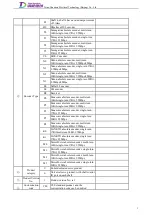
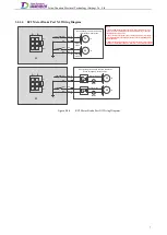
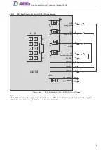
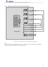
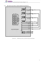
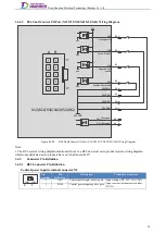
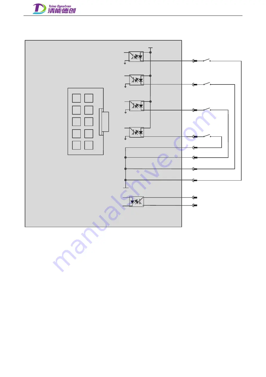
RC2 Shaft Control I/O Port (X12/X22) Wiring Diagram
24VGND
HDI1
DI1
DI2
B3
B4
GND
GND
GND
GND
B1
B2
B5
A5
24V
A4
A1
A2
A3
A4
A5
B1
B2
B3
B4
B5
A3
A2
A1
Homing switch
Negative limit
switch
Positive limit switch
24VGND
24VGND
24VGND
24VGND
DO+
A B
1
5
HDI2
DO-
Touch Probe 1
(Reserved)
(Reserved)
X12/X22
Figure 3.4-5.
RC2 Shaft Module I/O Port (X12/X22) Wiring Diagram
Note:
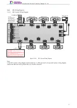
1. The RC2 system wiring diagram mentioned above is a RC2 universal servo product system wiring diagram,
while robot dedicated servo products have no "shaft control I/O".
8
Содержание EtherCAT CoolDrive RC Series
Страница 1: ...Updated on Update summary Updated version Version number D3 ...
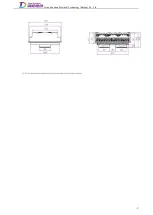
Страница 17: ...Tsino Dynatron Electrical Technology Beijing Co Ltd Dimension Drawing of RC3 2 3 2 7 ...
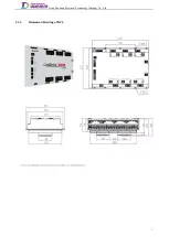
Страница 18: ...Tsino Dynatron Electrical Technology Beijing Co Ltd Dimension Drawing of RC4 2 3 3 8 ...
Страница 19: ...Tsino Dynatron Electrical Technology Beijing Co Ltd 9 ...
Страница 20: ...Tsino Dynatron Electrical Technology Beijing Co Ltd Dimension Drawing of RC6 2 3 4 1 ...

