Tsino-Dynatron Electrical Technology (Beijing) Co., Ltd.
Set the rotor compensation angle detection current through Byte2. As long as it does not exceed the maximum
allowable current of the motor and drive, the higher the detection current, the more accurate the detection result.
Set the phase sequence detection current through Byte3. As long as it does not exceed the maximum allowable
current of the motor and drive, under the same detection sensitivity, the higher the detection current, the higher the
success rate of the detection.
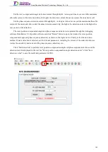
The rotor position compensation angle and phase sequence detection are operated through the debugging
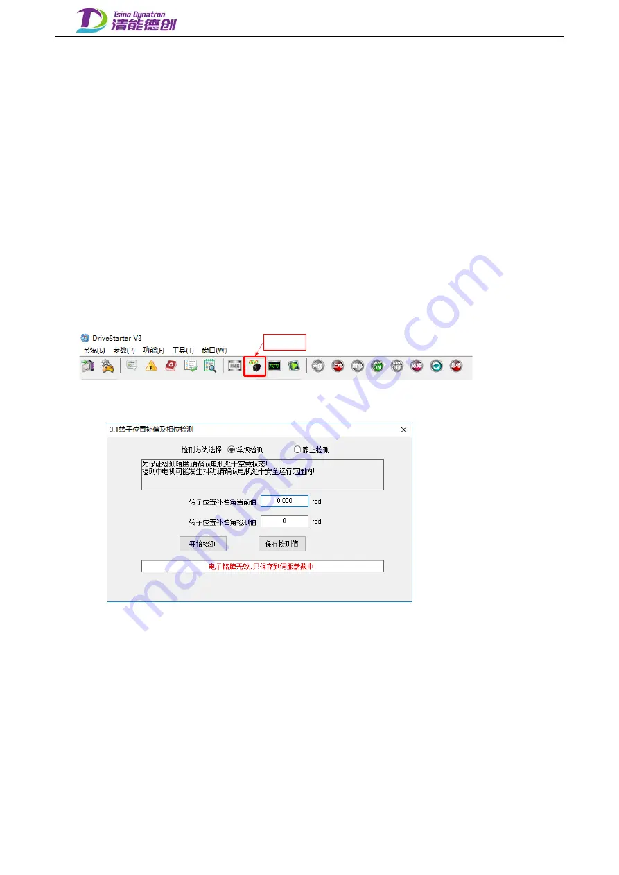
software DriveStarter V3. Open the software and click "Detect" button to open the window for rotor position
compensation angle and phase sequence detection, as shown in the figure below. Firstly, select the detection
method. If static detection is selected, set the relevant parameters, including the current of the static detection, as
well as the sensitivity and current of the phase sequence detection, etc..
Click "Start detection" to perform rotor position compensation angle and phase sequence detection, and the
detection result is displayed in the text box "Rotor position compensation angle detection value". Click "Save
detection value" to save the result into parameter 0x2003.
检测按钮
转子位置补偿角及相序检测窗口
184
Содержание EtherCAT CoolDrive RC Series
Страница 1: ...Updated on Update summary Updated version Version number D3 ...
Страница 17: ...Tsino Dynatron Electrical Technology Beijing Co Ltd Dimension Drawing of RC3 2 3 2 7 ...
Страница 18: ...Tsino Dynatron Electrical Technology Beijing Co Ltd Dimension Drawing of RC4 2 3 3 8 ...
Страница 19: ...Tsino Dynatron Electrical Technology Beijing Co Ltd 9 ...
Страница 20: ...Tsino Dynatron Electrical Technology Beijing Co Ltd Dimension Drawing of RC6 2 3 4 1 ...

