Tsino-Dynatron Electrical Technology (Beijing) Co., Ltd.
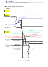
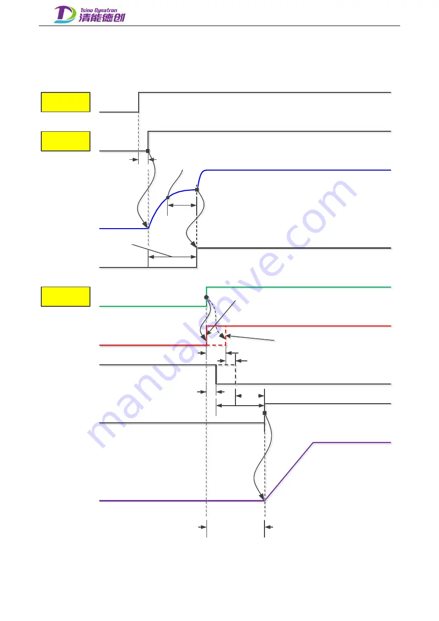
The servo ON/OFF timing diagram is shown as below:
Servo ON:
Control power
Power supply
DC bus voltage
Main power status
(0x6041.4)
Servo enabled
(0x6040.3)
Motor is working
(0x6041.2)
Motor braking
action
The target values
from upper control
system is valid
(0x6041.12)
Motor speed
0msec (min)
3sec
Drive enabled DC voltage
threshold (0x204D,No56)
Control power closed
Power supply closed
0
1
0: Servo disabled
1: Servo enabled
Motor brake activated
Motor brake released
0: Motor is not exciting
1: Motor is working
0: The host computer
command is invalid
1: The target values from upper
control system is valid
TMBR
TMBR
TMBRDLY: Motor Brake Release
Delay Time (0x2067,No152)
TMBR: Motor Brake Release
Time (0x2232,No164)
100msec
Servo enabling process:
Control word (0x6040.[3~0]) 0x06
→
0x0F
Servo enabling process:
Control word (0x6040.[3~0]) 0x06
→
0x07
→
0x0F
DC bus charging time
TMBRDLY
TMBRDLY
shaft - locked time
Figure 7.7-1.
Servo ON timing diagram
124
Содержание EtherCAT CoolDrive RC Series
Страница 1: ...Updated on Update summary Updated version Version number D3 ...
Страница 17: ...Tsino Dynatron Electrical Technology Beijing Co Ltd Dimension Drawing of RC3 2 3 2 7 ...
Страница 18: ...Tsino Dynatron Electrical Technology Beijing Co Ltd Dimension Drawing of RC4 2 3 3 8 ...
Страница 19: ...Tsino Dynatron Electrical Technology Beijing Co Ltd 9 ...
Страница 20: ...Tsino Dynatron Electrical Technology Beijing Co Ltd Dimension Drawing of RC6 2 3 4 1 ...

