Tsino-Dynatron Electrical Technology (Beijing) Co., Ltd.
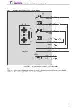
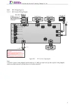
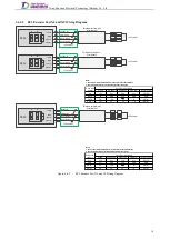
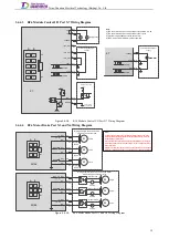
3.4.1.4
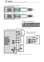
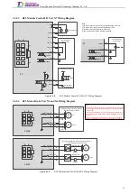
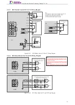
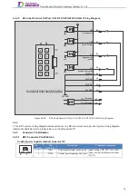
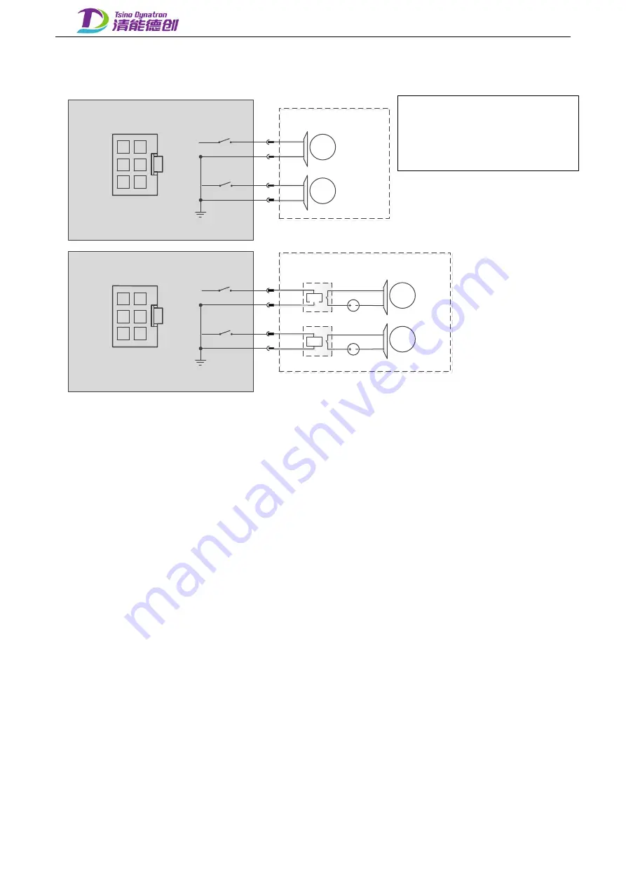
RC2 Motor Brake Port X3 Wiring Diagram
+24V
BK+
J2
+24V
BK+
J1
Note:
1. The maximum output current of the motor brake terminal is 1A. If the
current carried by the motor brake exceeds the allowed range, it must be
controlled by an external relay.
2. Do not short connect the BK+ end of each shaft, which may incur danger.
It is recommended to connect the BK+ and BK- to the corresponding motor
brakes separately.
3. Make sure the wiring sequence is correct, the connection is secure and the
insulation is reliable before power on, otherwise it may damage the product.
X3
A1
A2
A3
B1
B2
B3
A2
B2
A3
B3
BK-
BK-
A B
1
3
M
Motor
brake
-
+
M
Motor
brake
-
+
+24V
BK+
+24V
BK+
X3
A1
A2
A3
B1
B2
B3
A2
B2
A3
B3
BK-
BK-
A B
1
3
M
Motor brake
-
+
24VDC
KM
M
Motor brake
-
+
24VDC
KM
-
+
-
+
J2
J1
Wiring example: the drive directly
controls the motor brake
Wiring example: the drive controls the motor
brake through an external relay
Figure 3.4-4.
RC2 Motor Brake Port X3 Wiring Diagram
7
Содержание EtherCAT CoolDrive RC Series
Страница 1: ...Updated on Update summary Updated version Version number D3 ...
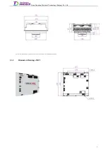
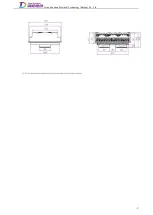
Страница 17: ...Tsino Dynatron Electrical Technology Beijing Co Ltd Dimension Drawing of RC3 2 3 2 7 ...
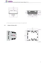
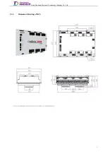
Страница 18: ...Tsino Dynatron Electrical Technology Beijing Co Ltd Dimension Drawing of RC4 2 3 3 8 ...
Страница 19: ...Tsino Dynatron Electrical Technology Beijing Co Ltd 9 ...
Страница 20: ...Tsino Dynatron Electrical Technology Beijing Co Ltd Dimension Drawing of RC6 2 3 4 1 ...


