Tsino-Dynatron Electrical Technology (Beijing) Co., Ltd.
Do not connect the power supply to the motor dynamic output terminals U, V, W.
The ground wire must be connected to the
terminal of the servo drive, which is usually copper wire
with a diameter more than 2.5 mm
2
(with mechanical protection).
Both the servo drive and motor must be reliably grounded for safety purpose.
For convenience of input side overcurrent protection and maintenance at outage, the servo drive should
be connected to the power supply through air switch or fuse switch.
Wiring
3.4
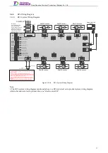
For safe and stable use of the servo drive, please observe the following precautions during wiring.
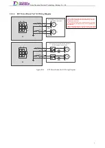
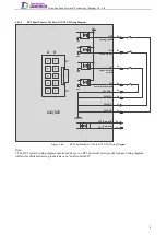
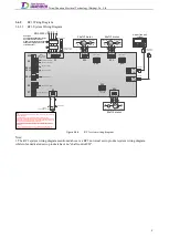
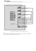
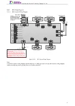
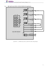
Do not connect the Power supply input to any other terminals except X1 terminal, which may damage the
product.
The input voltage of all terminals should not exceed the allowed range.
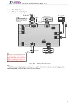
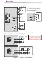
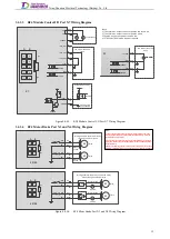
The maximum output current of the motor brake output terminal connector is 1Arms. If the current
carried by the motor brake exceeds the allowed range, it must be controlled by an external relay.
Do not short connect the BK+ end of each shaft, which may incur danger. It is recommended to connect
the BK+ and BK- to the corresponding motor brakes separately.
Make sure the wiring sequence is correct, the connection is secure and the insulation is reliable before
power on, otherwise it may damage the product.
When wiring the main circuit:
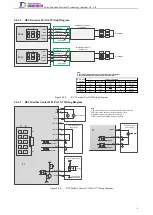
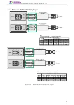
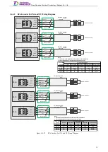
It is recommended to use the twisted-pair wire or multi-core twisted-pair overall shielded wire for the
input/output signal line and encoder cable.
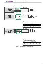
It is recommended that the length of the external IO signal line is no more than 3m, and the encoder cable
core and its length do not exceed the relevant values specified in table 2.2.3. If longer cables are required,
please contact our technical support for confirmation.
Do not press or damage the cable.
Dynamic cable should be wired separately with signal line and encoder cable.
Dynamic cable should be wired separately with dynamic output cable.
When connecting the ground wire:
In any case, the cross-sectional area of each protective conductor that is not part of the power cable or
cable sheath should not be less than:
2.5 mm
2
, with mechanical protection;
4 mm
2
, without mechanical protection. For the equipment connected with cable core, measures
should be taken to make the protective conductor in the cable core the last interrupted conductor
upon the failure of the stress relief mechanism.
Single-point ground is recommended.
When the servo motor and the machine are insulated from each other, connect the servo motor directly to
ground.
In addition, as the signal line and encoder cable core are very thin, please allow for some bend allowance during
wiring and do not have the cable stretched too tightly.
4
Содержание EtherCAT CoolDrive RC Series
Страница 1: ...Updated on Update summary Updated version Version number D3 ...
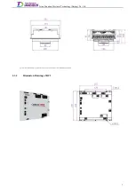
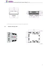
Страница 17: ...Tsino Dynatron Electrical Technology Beijing Co Ltd Dimension Drawing of RC3 2 3 2 7 ...
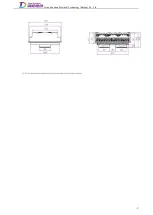
Страница 18: ...Tsino Dynatron Electrical Technology Beijing Co Ltd Dimension Drawing of RC4 2 3 3 8 ...
Страница 19: ...Tsino Dynatron Electrical Technology Beijing Co Ltd 9 ...
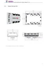
Страница 20: ...Tsino Dynatron Electrical Technology Beijing Co Ltd Dimension Drawing of RC6 2 3 4 1 ...


