background image

11-23

11

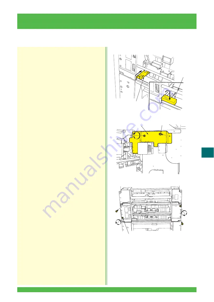
11.2 Back Printing Section

Removal

1. Remove the left cover 

(See Subsection 11.1.1)

.

2. Push the gear release lever and insert the spacer 

(approximately 2 cm) between the lever and the 

frame flange as shown.

3. Remove the two screws and then the harness 

cover.

4. Remove the four screws securing the unit.

11.2.1

Back Printing/Feed Unit Removal/Reinstallation

LII404

Gear Release Lever

Spacer

LII393

Screws (2)

Harness Cover

LII409

Screws (4)

Distributed by minilablaser.com

Содержание Frontier 570

Страница 1: ...CE MANUAL DIGITAL MINILAB FRONTIER 570 SCANNER IMAGE PROCESSOR SP 3000 LASER PRINTER PAPER PROCESSOR LP5700 Servicing and Electrical Circuit Diagram PP3 C1053E System Disk Ver 1 7 or later Distributed by minilablaser com ...

Страница 2: ...injury The dryer will be hot to the touch Wait 15 minutes after turning off the power before commencing with servicing procedures Wear gloves when handling the optical system parts to keep the parts free from fingerprints When mounting machine parts take care not to sandwich any of the wires Each of the connectors is provided with a symbol indicating what it is to be connected to Make sure the con...

Страница 3: ... CARRIER SECTION SCANNER SECTION SCANNER ELECTRICAL SECTION PAPER SUPPLY SECTION PAPER FEED SECTION EXPOSURE SECTION DISTRIBUTION PRINTER EXIT SECTION PROCESSOR SECTION PROCESSING SOLUTION CIRCULATION SYSTEM PROCESSING SOLUTION REPLENISHMENT SYSTEM DRYER SECTION PRINT EXIT SECTION SORTER ELECTRICAL SECTION ELECTRICAL CIRCUIT DIAGRAMS APPENDIX Distributed by minilablaser com ...

Страница 4: ...OM Drive Inspection 2 7 2 3 9 Printing Function Inspection 2 8 2 3 10 Cutter Inspection 2 9 2 3 11 Back Printing Head Inspection 2 9 2 3 12 Back Printer Head Replacement 2 9 2 3 13 Registration Section Feed Roller Cleaning 2 10 2 3 14 Nip Release Mechanism before exposure Inspection 2 11 2 3 15 Sub scanning Section Roller Cleaning 2 11 2 3 16 Cam Follower Rubber Bearing Replacement 2 12 2 3 17 Pip...

Страница 5: ...cs 3 179 3 3 11 Replenishment Level Sensor Diagnostics 3 180 3 3 12 Return Action after Replenishment System Error 3 180 3 3 13 Replenishment Cartridge Opening Malfunction 3 181 3 4 Restoration of Backup for Refreshing 3 182 3 5 OS Recovery and Backup for Refreshing 3 184 3 5 1 OS Recovery 3 184 3 5 2 Device Driver Installation 3 189 3 5 3 Backup for Refreshing 3 194 4 SOFTWARE INSTALLATION 4 1 4 ...

Страница 6: ... 43 5 4 3 Focus Position Adjustment 0321 5 43 5 4 4 Working Information Display 0322 5 44 5 4 5 AF Function Setup 0323 5 45 5 4 6 Dark Correction Bright Correction 0340 5 47 5 4 7 I O Check 0341 5 49 5 4 8 Carrier Inclination Display 0342 5 50 5 4 9 CCD Data Display 0343 5 51 5 4 10 Lens Registration 0344 5 53 5 4 11 Optical Axis Adjustment 0345 5 54 5 4 12 Optical Magnification Calibration 0346 5...

Страница 7: ...8 5 100 5 6 8 Printer I O Check 0540 5 101 5 6 9 Test Pattern Printing 0541 5 102 5 6 10 Laser Exposure Check 0542 5 104 5 6 11 R Laser R LD Data 0543 5 104 5 6 12 G Laser G SHG Data 0544 5 104 5 6 13 B Laser B LD Data 0545 5 105 5 6 14 Scan Scan Home Position Parameter 0546 5 105 5 6 15 Main Scan Laser Beam Sync Rough Adjust 0547 5 106 5 6 16 Laser Beam Sync Fine Adjustment Print 0548 5 107 5 6 1...

Страница 8: ...r 9941 5 139 5 11 3 Command 9942 5 140 6 OPERATION SECTION 6 1 Parts Location 6 2 6 1 Monitor 6 3 6 1 1 Monitor Replacement 6 3 6 2 Mouse Keyboard Light Box Optional 6 4 6 2 1 Mouse Replacement 6 4 6 2 2 Operation Keyboard Assembly Removal Reinstallation 6 4 6 2 3 Operation Keyboard Circuit Board Replacement 6 5 6 2 4 Operation Keyboard Replacement 6 5 6 2 5 Light Box Optional Replacement 6 6 6 2 ...

Страница 9: ...Replacement 7 40 7 2 12 IX240 Lower Dust Removal Roller Replacement 7 40 7 2 13 Slide Rail Replacement 7 41 7 2 14 Pressure Cover Open Close Sensor D128 Replacement 7 41 7 2 15 Harness Cover Removal Reinstallation 7 42 7 2 16 135 Leading End Sensor D101P DTG23 Circuit Board Replacement 7 42 7 2 17 IX240 Leading End Trailing End Bar Code Sensor D116P DTE23 Circuit Board Replacement 7 43 7 2 18 DTB2...

Страница 10: ...ement 7 82 7 5 4 MSB23 Circuit Board Replacement 7 84 7 5 5 Solenoid S480 Replacement 7 84 7 5 6 Mask Table Slider Position Sensor D486 Replacement 7 85 7 5 7 Mask Cover Gear Replacement 7 86 7 5 8 Plug in Connector Replacement 7 88 7 5 9 Slider Bracket Assembly Replacement 7 89 7 5 10 Mask Table Lock Unit Replacement 7 90 7 5 11 Mask Table Lock Unit Spring Replacement 7 91 7 6 Carrier Base Sectio...

Страница 11: ...ng to Scanner Circuit Board 8 25 8 2 18 Fixing Bracket Installation 8 29 9 SCANNER ELECTRICAL SECTION 9 1 Parts Location 9 2 9 1 Power Supply Section 9 3 9 1 1 Front Cover Removal Reinstallation 9 3 9 1 2 Rear Cover Removal Reinstallation 9 3 9 1 3 Start Switch D214 Replacement 9 4 9 1 4 Power Supply Unit Replacement 9 5 9 1 5 Power Supply Voltage Adjustment 9 6 9 2 Image Processing Circuit Board ...

Страница 12: ... 10 14 10 4 1 Upper Magazine Drive Unit Removal Reinstallation 10 14 10 4 2 Lower Magazine Drive Unit Removal Reinstallation 10 15 10 4 3 Upper Lower Magazine Paper Supply Motor M610 M620 Replacement 10 15 10 4 4 Drive Belt Replacement 10 16 10 4 5 Magazine Door Interlock Switch D680A B Replacement 10 17 11 PAPER FEED SECTION 11 1 Parts Location 11 3 11 1 Cutter Feed Section 11 6 11 1 1 Left Cover...

Страница 13: ...ck Printing Entrance Nip Roller Replacement 11 32 11 2 14 Back Printing Entrance Guide Plate Removal Reinstallation 11 33 11 2 15 Platen Replacement 11 34 11 2 16 Back Printing Surface Side Guide Plate Replacement 11 34 11 2 17 Back Printing Drive Gear Replacement 11 35 11 2 18 Back Printing Head Replacement 11 36 11 2 19 Back Printing Unit Removal Reinstallation 11 37 11 2 20 Back Printing Unit D...

Страница 14: ...Replacement 12 15 12 3 Sub scanning Unit 12 17 12 3 1 Sub scanning Unit Removal Reinstallation 12 17 12 3 2 Frame Removal Reinstallation 12 18 12 3 3 Sub scanning Steel Belt Replacement 12 19 12 3 4 Sub scanning Feed Motor M650 Replacement 12 21 12 3 5 Timing Belt Replacement 12 21 12 3 6 Soft Nip Motor M651 Replacement 12 22 12 3 7 Rubber Flat Belt Replacement 12 22 12 3 8 Soft Nip Home Position ...

Страница 15: ...13 36 13 2 14 Distribution Section Paper Sensor Front D664P Center D660P Rear D665P Replacement 13 36 13 2 15 Distribution Section Paper Sensor LED Front D664L Center D660L Rear D665L Replacement 13 37 13 2 16 Pipe Slider Replacement 13 38 13 2 17 Distribution Section Drive Standby Sensor D669 Replacement 13 40 13 2 18 Drive Gear with Torque Limiter Replacement 13 40 13 2 19 Nip Roller Guide Plate...

Страница 16: ...System 14 25 14 4 1 Right Cover Removal Reinstallation 14 25 14 4 2 Processor Rear Cover Removal Reinstallation 14 25 14 4 3 Motor Driver Bracket Removal Reinstallation 14 26 14 4 4 Motor Driver Replacement 14 27 14 4 5 Auto Chain Tensioner Removal Reinstallation 14 27 14 4 6 Processor Drive Motor M700 Replacement 14 28 14 4 7 Drive Bracket Removal Reinstallation 14 29 14 4 8 Drive Sprocket Gear R...

Страница 17: ...tallation 16 7 16 1 7 Cartridge Opening Motor M720 Replacement 16 8 16 1 8 Replenisher Box Door Lock Manual Releasing 16 9 16 2 Processing Solution Replenishment System 16 10 16 2 1 Replenisher Filter Replacement 16 10 16 2 2 P1R P2RA P2RB Pump PU721 PU722 PU723 Replacement 16 10 16 2 3 PSR Pump Bracket Removal Reinstallation 16 12 16 2 4 PSR Pump PU724 Replacement 16 13 16 2 5 PSR Pump Valve Repl...

Страница 18: ...ing Paper Sensor LED Rear Center Front D770L D771L D772L Lower Exit Paper Sensor LED Rear Center Front D773L D774L D775L Replacement 18 12 18 1 5 Feeding Path Switching Paper Sensor Rear Center Front D770P D771P D772P Replacement 18 13 18 1 6 Lower Exit Paper Sensor Rear Center Front D773P D774P D775P Replacement 18 13 18 1 7 Feeding Path Switching Solenoid S770 Replacement 18 14 18 1 8 Feeding Pa...

Страница 19: ... Replacement 18 48 18 6 5 Sorter Right Lower Cover Removal Reinstallation 18 48 18 6 6 Sorter Left Upper Lower Cover Removal Reinstallation 18 49 18 6 7 Sorter Full Sensor D811 Replacement 18 50 18 6 8 Chain Tension Adjustment 18 50 18 6 9 Sorter Tray Step Position Adjustment 18 51 19 ELECTRICAL SECTION 19 1 Parts Location 19 2 19 1 Power Input Section 19 3 19 1 1 Built in Circuit Breaker Replacem...

Страница 20: ...acement 19 34 20 ELECTRICAL CIRCUIT DIAGRAMS 20 1 20 1 I O Parts Diagrams 20 2 20 1 1 Scanner Section SP 3000 20 2 20 1 2 Auto Film Carrier NC100AY 20 4 20 1 3 Multi film Carrier MFC10AY 20 6 20 1 4 Printer Section LP5700 20 7 20 1 5 Processor Section LP5700 20 11 20 2 Electrical Parts and Circuit Board Layout Diagrams 20 15 20 2 1 Scanner Section SP 3000 20 15 20 2 2 Printer Section LP5700 20 16 ...

Страница 21: ...1 20 7 7 LDD23 Circuit Board Wiring Diagram 20 63 20 7 8 Image Control Box Circuit Board Wiring Diagram 20 64 20 7 9 PDA23 Circuit Board Wiring Diagram 20 65 20 7 10 PDB23 Circuit Board Wiring Diagram 20 67 21 APPENDIX 21 1 21 1 Adjustment Jigs 21 2 21 1 1 Auto Film Carrier NC100AY 21 2 21 1 2 LP5700 21 4 21 2 Required Adjustments after Parts Replacement 21 5 21 2 1 Auto Film Carrier NC100AY 21 5 ...

Страница 22: ...enu Table 1 6 1 2 2 0 MENU Item 1 7 1 2 3 1 STARTUP CHK Item 1 8 1 2 4 2 END CHK Item 1 10 1 2 5 3 LANGUAGE Item 1 11 1 2 6 4 CHECK Item 1 12 1 2 7 5 SELECT FUNC Item 1 13 1 2 8 6 PRINT COND Item 1 14 1 2 9 7 SPECIAL PRINT Item 1 15 1 2 10 8 SYSTEM Item 1 16 1 2 11 9 INSTALLATION Item 1 19 Distributed by minilablaser com ...

Страница 23: ...ormation Reference K 02 Print Condition Setup and Check 0200 Paper Condition Setup K K K 0220 Print Size Setup K K 0221 Paper Magazine Registration K K 0222 Monitor Adjustment K K 0223 Special Film Channel Setting K K 0224 Monotone Correction Setting K K 0225 Custom Setting Regist Delete K K 0226 Back Printing Format K K 0227 Index Conditions K K 0240 Image Correction Setup K 0241 Fine Adjustment ...

Страница 24: ...rmation Display K K 0425 NC100AY Monitor Frame Ratio Setup K K 0426 MFC10AY Monitor Frame Ratio Setup K K 0440 NC100AY Sensor Calibration K 0441 NC100AY Focus Offset Adjustment K 0442 MFC10AY Focus Offset Adjustment K 0443 NC100AY Sensor Calibration Information K 0444 NC100AY Installation Information Display K 0445 MFC10AY Installation Information Display K 0446 NC100AY Installation Information Se...

Страница 25: ... 0546 Scan Scan Home Position Parameter K 0547 Main Scan Laser Beam Sync Rough Adjustment K 0548 Laser Beam Sync Fine Adjustment Print K 0549 Laser History Display K 0550 Paper Condition Setup Table LUT Copy K 0551 Printer Mechanical Fine Adjustment K 0552 Filter Replacement History K 0553 Feeding Position Sensor Fine Adjustment K 0554 Image Position Initial Setting K 0555 Sub Scan Feeding Speed A...

Страница 26: ...formation Display K K 0740 Image Processing Section I O Check K 0741 Image Processing Section Function Setting K 10 Register Delete 1020 Shop Logo Regist Delete K K 1021 Template Regist Delete K K 1022 Holiday File Regist Delete K K 1023 Custom Button Regist Save K K 21 Help 2140 Trouble Help SE K 22 Self Diagnostics Scanner 2240 Image Processing Circuit Board Check K 2241 Image Data Diagnostics K...

Страница 27: ... FUNC 51 POWER OFF Power supply OFF K K 6 PRINT COND 61 CALIBRATION Condition upkeep printing K K 62 MEASURE DENS Density measurement K K 7 SPEC PRINT 71 TEST PATTERN Pattern printing K K 8 SYSTEM 81 PROC TYPE Processor type selection K 82 PROC METHOD Processing method selection K 83 SORTER TYPE Sorter type selection K 84 NIGHT ALARM Night alarm ON OFF K 85 SET AREA K 9 INSTALLATION 91 PSR AIR EXT...

Страница 28: ...ee Subsection 1 2 8 0 MENU 7 SPEC PRINT 7 SPEC PRINT 1 TEST PATTERN See Subsection 1 2 9 See Subsection 1 2 10 See Subsection 1 2 11 0 MENU 8 SYSTEM 8 SYSTEM 1 PROC TYPE INITIALIZE 0 MENU 2 END CHK 0 MENU 1 STARTUP CHK 2 END CHK 1 CHK START See Subsection 1 2 4 1 STARTUP CHK 1 PROC TEMP See Subsection 1 2 3 ENTER MENU MENU MENU MENU MENU MENU See Subsection 1 2 3 See Subsection 1 2 4 See Subsectio...

Страница 29: ...n Panel Menu Table 1 2 3 1 STARTUP CHK Item 11 PROC TEMP PS4 30 5 11 PROC TEMP DRY 30 5 11 PROC TEMP PS2 30 5 11 PROC TEMP P2 30 5 11 PROC TEMP P1 30 5 1 STARTUP CHK 1 PROC TEMP 0 MENU 1 STARTUP CHK ENTER Distributed by minilablaser com ...

Страница 30: ...TARTUP CHK 3 MEASURE DENS ENTER 13 MEASURE DENS LUT UPDATE NG ENTER 13 MEASURE DENS START 13 MEASURE DENS MEASURING Ixxxx Cancel YES Ixxxx Cancel NO 14 CTRL STRIPS PROCESSING 1 STARTUP CHK 4 CTRL STRIPS ENTER ENTER ENTER 14 CTRL STRIPS START xxxxx xxxxx Set Holder DRIVE YES Set Holder DRIVE NO MEASURE DATA NORMAL MEASURE DATA ABNORMAL MEASURE DATA RECEPTION CONDITION NG CONDITION OK ENTER Distribu...

Страница 31: ...em 0 MENU 2 END CHK 2 END CHK 1 CHK START 21 STARTUP TIME 07 01 04 09 00 M002 Cancel YES M002 Cancel NO 21 CHK START CHECKING 21 STARTUP TIME 07 01 03 09 00 ENTER ENTER ENTER ENTER 21 RACK WASH CLEANING POWER OFF Only the date rises descends Distributed by minilablaser com ...

Страница 32: ...5 3 LANGUAGE Item 0 MENU 3 LANGUAGE 3 LANGUAGE 2 ORG LANG NO 3 LANGUAGE 3 ADD LANG NO 3 LANGUAGE 1 SET LANG ENTER 31 SET LANG Japanese 32 ORG LANG No 000003 33 ADD LANG No NO LANG LOADED 31 SET LANG English ENTER ENTER ENTER ENTER Distributed by minilablaser com ...

Страница 33: ... Operation Panel Menu Table 1 2 6 4 CHECK Item 0 MENU 4 CHECK 4 CHECK 1 PROC TEMP 41 PROC TEMP P2 43 0 41 PROC TEMP PS2 45 0 41 PROC TEMP PS4 45 0 41 PROC TEMP P1 43 0 ENTER 41 PROC TEMP DRY 31 6 Distributed by minilablaser com ...

Страница 34: ...r Operation Panel Menu Table 1 1 2 7 5 SELECT FUNC Item 0 MENU 5 SELECT FUNC 5 SELECT FUNC 1 POWER OFF 51 POWER OFF START M0003 POWER OFF YES M0003 POWER OFF NO ENTER ENTER ENTER ENTER POWER OFF Distributed by minilablaser com ...

Страница 35: ...MEASURE DENS START 62 MEASURE DENS MEASURE M0002 Cancel NO 61 CALIBRATION MAG UPPER 61 CALIBRATION PRINTING 61 CALIBRATION COMPLETED 61 CALIBRATION START ENTER ENTER ENTER ENTER ENTER ENTER ENTER ENTER ENTER 62 MEASURE DENS LUT UP DATE NG 62 MEASURE DENS LUT UP DATE OK M0002 Cancel YES MEASURE DATA NORMAL MEASURE DATA ABNORMAL MEASURE DATA RECEPTION Distributed by minilablaser com ...

Страница 36: ...TH 381 0 71 TEST PATTERN START 71 TEST PATTERN PRINTING 71 TEST PATTERN COMPLETED 71 TEST PATTERN LENGTH 457 0 ENTER ENTER ENTER 0 MENU 7 SPEC PRINT 71 TEST PATTERN LENGTH 254 0 71 TEST PATTERN TYPE GRID 71 TEST PATTERN TYPE BL Plas 71 TEST PATTERN TYPE BD Plas 71 TEST PATTERN TYPE ZIBKPrint 71 TEST PATTERN TYPE LIBKPrint 71 TEST PATTERN TYPE Pap Feed 71 TEST PATTERN TYPE Grad 71 TEST PATTERN TYPE...

Страница 37: ...EM 1 PROC TYPE 8 SYSTEM 2 PROC METHOD 8 SYSTEM 3 SORTER TYPE 8 SYSTEM 4 NIGHT ALARM See 81 PROC TYPE See 82 PROC METHOD See 83 SORTER TYPE See 84 NIGHT ALARM 8 SYSTEM 5 SET AREA See 85 SET AREA 8 SYSTEM 1 PROC TYPE 81 PROC TYPE LP5700 81 PROC TYPE PRO Entry chk ENTER ENTER ENTER Distributed by minilablaser com ...

Страница 38: ... PROC METHOD 83 SORTER TYPE ENTER ENTER 8 SYSTEM 2 PROC METHOD 82 PROC METHOD FACTORY TEST 82 PROC METHOD CP 49E ENTER ENTER ENTER ENTER 8 SYSTEM 3 SORTER TYPE 83 SORTER TYPE 14 ORDER 83 SORTER TYPE 24 ORDER 83 SORTER TYPE NONE Distributed by minilablaser com ...

Страница 39: ...able 84 NIGHT ALARM 85 SET AREA ENTER ENTER ENTER 8 SYSTEM 4 NIGHT ALARM 84 NIGHT ALARM OFF 84 NIGHT ALARM ON ENTER ENTER ENTER ENTER 8 SYSTEM 5 SET AREA 85 SET AREA North America 85 SET AREA Europe 85 SET AREA Standard Distributed by minilablaser com ...

Страница 40: ... 9 INSTALLATION 2 MIX REPL 9 INSTALLATION 1 PSR AIR EXT 0 MENU 9 INSTALLATION 91 PSR AIR EXT START 92 MIX REPL START 93 PUMP AIR EXT START 94 IP ADDR SET 223000000000 95 NET MASK SET 223000000000 ENTER ENTER 9 INSTALLATION 5 NET MASK SET 9 INSTALLATION 4 IP ADDR SET 94 IP ADDR SET 123000000000 95 NET MASK SET 123000000000 It moves to a right beam Number change It moves to a right beam Number chang...

Страница 41: ...anism before exposure Inspection 2 11 2 3 15 Sub scanning Section Roller Cleaning 2 11 2 3 16 Cam Follower Rubber Bearing Replacement 2 12 2 3 17 Pipe Slider Inspection 2 13 2 3 18 Distribution Section Nip Release System Roller Inspection 2 13 2 3 19 Processing Rack Helical Drive Gear Lubrication 2 14 2 3 20 Crossover Rack Dryer Entrance Rack Auto Washing Nozzle Inspection 2 14 2 3 21 Circulation ...

Страница 42: ...inter Power Supply Section Air Filters Clean Printer Processor Processing Solution Cooling Fan Air Filter Clean Printer Processor Dryer Section Air Filters Clean Printer Processor Dryer Exit Section Air Filter Clean Printer Processor P1 P2 Circulation Filters Replace Printer Processor Processing Racks Wash Printer Processor Auto washing Nozzles Clean Printer Processor Paper Feed Section Rollers Cl...

Страница 43: ...cessing Rack Helical Drive Gears Grease Subsection 2 3 19 P1R P2RA P2RB Pump Output Leaks Inspect Subsection 5 7 1 PSR Pump Output Leaks Inspect Subsection 5 7 1 PSR Pump Bellows Valve Replace Subsection 16 2 6 for bellows Subsection 16 2 5 for valve Crossover Rack Auto Washing Nozzle Inspect Subsection 2 3 20 Dryer Entrance Rack Auto Washing Nozzle Inspect Subsection 2 3 20 PS Tank Separate Plate...

Страница 44: ...emove any dirt or dust adhering to the rollers using a cotton swab moistened with alcohol solution mixture of an equal amount of alcohol and water 5 Reinstall the ball and cover 1 Make sure that the carrier maintenance operations are executed correctly by the customer 2 Clean the sensors on the carrier and check them for scratches or cracks 3 Clean the plug in connector using the blower brush 2 3 ...

Страница 45: ...Remove any dirt or dust adhering to the power supply cord using a cloth moistened with water Removal 1 Remove the carrier 2 Remove two screws each and then the right hand and left hand slider guides Installation Installation is essentially in the reverse order of removal 2 3 4 Carrier Base Slider Rail Cleaning Z2580 Slider Rails 2 3 5 Power Supply Cord Cleaning 2 3 6 Carrier Base Slider Guide Repl...

Страница 46: ...Processor for Destination 5 Click the OK button 6 Click the Cancel button after backup is completed Operation returns to the menu screen 7 Proceed to Menu 9941 Explorer 8 Double click the My Computer and 3 5 inch FD icons 9 Make sure there are the three files in the floppy disk 10 Exit the Explorer screen 2 3 7 Floppy Disk Drive Inspection Z2041 Formatted Floppy Disk Distributed by minilablaser co...

Страница 47: ... CD ROM tray is ejected 2 Press the CD ROM eject button The CD ROM tray returns NOTE If the CD ROM tray does not operate properly after Steps 1 and 2 are taken the CD ROM drive may be defective Z2042 2 3 8 CD ROM Drive Inspection Z2534 CD ROM Tray CD ROM Eject Button Z2535 CD ROM Tray CD ROM Eject Button Distributed by minilablaser com ...

Страница 48: ...ay 7 Check the color drift for the C M and Y lines at the center of the print using a magnifying lens 20 to 40 If the color drift exceeds 1 3 of the color line thickness perform the following maintenance operations Menu 0547 Main Scanning Position Adjustment Laser Beam Sync Rough Adjustment See Subsection 5 6 15 Menu 0548 Laser Beam Sync Fine Adjustment Print See Subsection 5 6 16 Menu 0554 Image ...

Страница 49: ...k the back printing again 2 If the back printing is still abnormal replace the back printer head See Subsection 2 3 12 Removal 1 Open the magazine door 2 Loosen the screw and move the back printer unit to the right side Then retighten the screw 3 Push the locking tab and remove the ink ribbon cassette 4 Remove the screw and then the connector cover 2 3 10 Cutter Inspection 2 3 11 Back Printing Hea...

Страница 50: ...ust the printer head clearance See Subsection 11 2 21 1 Remove the registration unit See Subsection 11 3 1 2 Wipe the feed and nip rollers clean with a cloth moistened with water while turning the knob or gear as shown 3 Reinstall the registration unit See Subsection 11 3 1 L2929 Connector Screws 2 Printer Head 2 3 13 Registration Section Feed Roller Cleaning L2930 L2931 Knob Rollers Rollers Gear ...

Страница 51: ... Subsection 12 3 1 2 Open the clamp and disconnect the three connectors 3 Remove the six screws and then the bracket 4 Wipe the lower nip rollers clean with a cloth moistened with water while turning the knob 5 Reinstall the bracket 2 3 14 Nip Release Mechanism before exposure Inspection L2932 Nip Release Solenoids 4 2 3 15 Sub scanning Section Roller Cleaning L2933 Clamp Connectors 3 Screws 6 Bra...

Страница 52: ...heet of paper to turn them 8 Reinstall the sub scanning unit See Subsection 12 3 1 Removal 1 Remove the sub scanning unit See Subsection 12 3 1 2 Remove the frame from the sub scanning unit See Subsection 12 3 2 3 Remove the three screws and then the timing belt cover L2935 Knob Feed Rollers L2936 Paper Cotton Swab Scanning Rollers 2 3 16 Cam Follower Rubber Bearing Replacement L2436 Screws 3 Timi...

Страница 53: ... If there are scores on the slider shaft caused by the sliding balls the pipe slider is no problem if it slides smoothly 4 Close the distribution section guide plate 1 Open the magazine door 2 Open the distribution section guide plate 3 Check the nip rollers are free from foreign matter and for smooth operation by turning them 4 Close the distribution section guide plate L21155 Cam Followers 2 E r...

Страница 54: ...Stopper 2 yellow 2 Remove the No 1 to No 3 crossover and dryer entrance racks 3 Check the auto washing nozzles for clogging and clean them using a toothbrush if necessary 4 Reinstall the dryer entrance and No 1 to No 3 crossover racks 5 Close the dryer unit 2 3 19 Processing Rack Helical Drive Gear Lubrication L2939 Rack Drive Gears 6 GREASE 2 3 20 Crossover Rack Dryer Entrance Rack Auto Washing N...

Страница 55: ...ion pumps and check that the pumps are operating normally 4 Reinstall the processor front cover See Subsection 15 1 1 1 Start up the system and open Menu 4 Processor Solution Temperature Check screen in the pre operational checks 2 Check that the temperatures increase normally 3 If the temperature increases slowly or does not rise either the circulation filter is clogged or the safety thermostat o...

Страница 56: ...unit and support it using Stopper 2 yellow 6 Remove the screw and then the processing solution level sensor from the sub tank 7 Wipe dirt off each processing solution level sensor with a cloth moistened with water 8 Reinstall the removed parts 9 Close the dryer unit 2 3 23 Processing Solution Level Sensor Cleaning L21051 Screw Splash prevention Cover L21127 Screw Solution Level Sensor L21128 Solut...

Страница 57: ...t 3 Remove the two screws and then the level sensor 4 Wipe dirt off each replenisher level sensor with a cloth moistened with water 5 Reinstall the removed parts 2 3 24 Replenisher Level Sensor Cleaning L21131 Screws 2 Replenisher Tanks L21132 Screws 2 P1R Replenisher level Sensor P2RA P2RB L21133 Replenisher Level Sensor Distributed by minilablaser com ...

Страница 58: ...nstall the removed parts 1 Perform the post operational checks to shut down the system and turn OFF the built in circuit breaker and main power supply 2 Open the dryer unit and support it using Stopper 2 yellow 3 Remove the screw and then the waste solution level sensor cover 2 3 25 PS4 Solution Concentration Sensor Cleaning L21129 Screw PS4 Solution Concentration Sensor PS4 Solution Concentration...

Страница 59: ... Wipe dirt off the waste solution level sensor with a cloth moistened with water 7 Reinstall the removed parts 1 Open the Menu 0624 Processor Input Check screen 2 Remove the right cover See Subsection 14 4 1 L21191 Flashlight Slits Peep Holes Connector Tank Cap L21130 Waste Solution Tank Cap Waste Solution Level Sensor 2 3 27 PSR Level Sensor Inspection Distributed by minilablaser com ...

Страница 60: ...4 1 2 Check the processor bottom pan for any sign of solution leakage 3 Check the solution circulation system and replenisher system for 1 Any sign of solution leakage at each joint 2 Loose hose clamps 3 Collapsed bent or cracked hoses 4 If necessary repair or replace parts 5 Reinstall the removed covers L21151 PSR Lower Level Sensor PSR Upper Level Sensor 2 3 28 Solution Hose and Clamp Inspection...

Страница 61: ...1G02003 4 Reinstall the crossover racks 1 Remove the dryer belt unit See Subsection 17 2 1 2 Check the mesh belt for damage or fouling by turning it with hand Replace the mesh belt if it is damaged Clean the mesh belt if it is fouling 3 Reinstall the dryer belt unit See Subsection 17 2 1 2 3 29 Processor Drive Chain Lubrication L2941 Chain GREASE 2 3 30 Dryer Mesh Belt Inspection L21194 Dryer Mesh...

Страница 62: ...ty 3 172 3 3 7 Processing Solution Tank Level Lowering 3 176 3 3 8 Replenishment Pump Diagnostics 3 177 3 3 9 Rack Auto Cleaning System Diagnostics 3 178 3 3 10 P1R Stirring Valve Replenishment Cartridge Washing Valve Diagnostics 3 179 3 3 11 Replenishment Level Sensor Diagnostics 3 180 3 3 12 Return Action after Replenishment System Error 3 180 3 3 13 Replenishment Cartridge Opening Malfunction 3...

Страница 63: ...te a report in the specified format 3 1 1 Message Number Symbol Error E Trouble Error requires action of the service representative W Mismatching of condition Error can be corrected by the operator I Information X Software trouble 3 1 2 Message Icon Icon Error Errors with code E Take measures after turning OFF the power supply Errors with code E W or X Error can be recovered For code I Information...

Страница 64: ...ng of image Do the pre scan again Error occurred during auto setup Causes of the error message 1 Software failure 2 Hard disk malfunction 3 Main control unit malfunction 1 Restart system and if problem persists reinstall system software NOTE 1 2 Replace the HDD 3 Replace main control unit W 1418 not installed or paper end processing in progress Install the magazine and then start printing Magazine...

Страница 65: ...ystem software failure 1 Connect 1394 cable correctly or replace it 2 Restart system and if problem persists reinstall system software NOTE 1 W 1428 A communication error occurred between the main control section and printer processor Check the connection and then press the Retry button Error returned when the magazine status retrieving command is issued to printer at start up Causes of the error ...

Страница 66: ...to D625 1 Change the print size or template 2 Replace the sensor E 1482 Hard disk failure occurred Consult technical representative Hard disk fault is detected when file is imported from or exported to the Imaging Controller Causes of the error message 1 Faulty hard disk in main control unit 1 Replace the HDD of the main control unit E 1483 Index image data cannot be read Consult technical represe...

Страница 67: ... selected screen To use this function consult your technical representative This message appears when the files required to display image cannot be read Causes of the error message 1 Write protected FD 2 System software failure 3 Main control unit failure 1 Set the FD to the write enable mode 2 Restart system and if problem persists reinstall system software NOTE 1 3 Replace the main control unit ...

Страница 68: ...24 Couldn t read the backup data for PU800B Check the connection with PU800B File reading error occurred in downloading from PU800B Causes of the error message 1 System software failure 2 Main control unit failure 1 Restart system and if problem persists reinstall system software NOTE 1 2 Replace main control unit W 1525 Couldn t write to the backup data for PU800B Check the connection with PU800B...

Страница 69: ...y Imaging Controller software 1 Connect the LAN cable correctly 2 Restart or reinstall the Imaging Controller software E 1536 Error occurred during the order completion Incorrect order status Change the status in the Imaging Controller Inappropriate status no device authority Causes of the error message 1 Faulty Imaging Controller software 1 Restart or reinstall the Imaging Controller software E 1...

Страница 70: ...hange when no order is read Causes of the error message 1 Poorly connected LAN cable 2 Faulty Imaging Controller software 1 Connect the LAN cable correctly 2 Restart or reinstall the Imaging Controller software W 1547 Couldn t provide the service Check the network connections and then press the Retry button Error caused by reading order Causes of the error message 1 Poorly connected LAN cable 2 Fa...

Страница 71: ...t software B1 3 Faulty hard disk 1 Reinstall the software NOTE 1 2 Reinstall the software 3 Replace the HDD of the main control unit W 1556 This frame cannot be selected Frame No to specify template not matched Select another frame again Frame number of mounted print mismatched Causes of the error message 1 Large index or template frame number mismatched 2 Frame number reading failed 1 Enter the c...

Страница 72: ... is not detected Check the film I 1593 Please wait Template setup is in progress I 1594 Reading service name list Please wait This message appears while reading the service name list for image file export import Wait until saving is completed I 1595 Start the connection with Imaging Controller and update the data Use digital imaging service without Imaging controller update the inside data Press O...

Страница 73: ...e This message appears when an error occurs due to a network disconnection during reading of order in auto printing mode Causes of the error message 1 The Imaging Controller power is turned off 2 Poorly connected LAN cable 3 Faulty software on the imaging controller 4 Faulty PC on the imaging controller side 1 Start the Imaging controller 2 Connect the LAN cable correctly 3 Reinstall the software ...

Страница 74: ... Manual Correct Setup 1 Wait until completing free cropping 2 Select below Lens Auto Correction OFF Lens Manual Correct Setup Lens type No 0 No W 1740 Cannot perform the free cropping because the lens correction was done This message shows that free cropping cannot be performed when the lens correction was done Lens Auto Correction OFF Lens Manual Correct Setup Lens type No 0 No After rescanning s...

Страница 75: ...ed print or frame character is being displayed 9 The batch retrieval of exposure conditions is in progress 10 Negative sheet index screen is being displayed or print is being processed 11 The Red eye Soft Cross plug in is starting 1 Wait until the template setting finishes 2 Select the output destination using the Output destination selection screen 3 Close the Original selection screen 4 Select t...

Страница 76: ...en 10 Wait until the negative sheet index screen is closed or processing is completed 11 Quit the Red eye Soft Cross plug in screen W 1754 Couldn t provide the service Check the network connections If the network connections are correct consult your technical representative An error occurred while a service name list was being read Causes of the error message 1 The DI controller power is turned of...

Страница 77: ...e menu setting file This message appears when value written in the service menu setting file exceeds the range Set up the file correctly E 1774 Cannot perform the DI service registered in the Service Menu This message appears when the digitizing service that was registered in the service menu setting file cannot be found in the Imaging Controller Change the service menu setup file to the optimum s...

Страница 78: ...1787 The magazine is not installed properly Install it properly This message appears when the magazine is not installed properly when the service menu button is pressed Install the paper magazine I 1788 The frame information will be discarded OK This message appears when the service menu button is pressed when you select the frame E 1789 Couldn t open the function key setting file This message app...

Страница 79: ... is pressed Install the mask correctly W 1800 The mask for is not installed Replace it and then select the service menu again The correct mask is not installed The incorrect mask is installed when printing operation starts or the service menu button is pressed Install the correct mask W 1801 135 Reversal Film was selected Remove the 135 insertion section upper guide during processing the 135 Rever...

Страница 80: ... carrier Incorrect mask is installed for one way mode Install the correct carrier I 1921 You cannot return to the main menu screen during processing of the image After it is completed return to the main menu screen Printing operation is terminated during image processing Wait until processing is completed W 1922 When the format type is the current paper width and the print size selected as index f...

Страница 81: ...r message 1 Built in breaker on the LP5700 is OFF 2 Poorly connected or broken 1394 grounding clamp 3 Abnormal software 4 Faulty main control unit 1 Turn ON the built in circuit breaker to restart the system 2 Connect the clamp correctly or replace 3 Restart the system If the problem persists reinstall system software NOTE 1 4 Replace the main control unit W 2110 Communication error occurred betwe...

Страница 82: ...Please Wait Causes of the error message 1 The maintenance is started during the printer is processing 1 Wait until processing is completed W 2211 Performing evaporation correction Please Wait Causes of the error message 1 The maintenance is started during performing the evaporation correction 1 Wait until the evaporation correction is completed W 2213 Printing not performed due to lack of conditio...

Страница 83: ... switch turned ON Causes of the error message 1 The power switch is ON 1 Turn the power switch to STANDBY E 2312 Timer in printer abnormal so it was initialized If problems persist consult your technical representative During system startup abnormality of the RTC device has been detected The default value 1980 01 01 is set Causes of the error message 1 GPR backup switch is OFF 2 Discharged backup ...

Страница 84: ...normal Shut down scanner with emergency stop button and restart it If problems persist consult your technical representative Rotation of the image control section cooling fan F620 is not detected Causes of the error message 1 Poorly connected or broken harness between the image control section cooling fan F620 and GMC4 on the GMC23 circuit board 2 Faulty F620 3 Faulty GMC23 circuit board 1 Connect...

Страница 85: ...the harness correctly or repair or replace it 2 Replace F630 3 Replace the PAC23 circuit board W 2401 Paper jam occurred in upper supply section 1 Check it NUM sheets remain Press Help button to see error help or manual Remove paper while referring to it D619 sensor does not detect the leading end of paper within a specified time after the paper has been drawn from the upper paper magazine Causes ...

Страница 86: ...eplace the PDA23 circuit board 8 Replace the CTL23 circuit board W 2403 Paper jam occurred in cutter feed section 3 Check it sheets remain Press Help button to see error help or manual Remove paper while referring to it D631 sensor does not detect the leading end of paper within a specified time after D619 sensor detects the leading end of paper D632 sensor does not detect the leading end of paper...

Страница 87: ...it 3 Replace D633 4 Replace M631 5 Replace M632 6 Replace the PDA23 circuit board W 2405 Paper jam occurred in registration section 5 Check it sheets remain Press Help button to see error help or manual Remove paper while referring to it D650 sensor does not detect the leading end of paper within a specified time after D633 or D640 sensor detects the leading end of paper Causes of the error messag...

Страница 88: ...Poorly connected or broken harness between the upper magazine paper supply motor M610 and PDA3 on the PDA23 circuit board 5 Faulty D619 6 Faulty M610 malfunction 7 Faulty PDA23 circuit board 8 Faulty CTL23 circuit board 1 Load another magazine and if paper rewind is normally done replace the old magazine 2 Clean the magazine rollers 3 Connect the harness correctly or repair or replace it 4 Connect...

Страница 89: ... paper jam occurs in the printer section this problem is solved by removing the paper Shut down scanner with emergency button and restart it If problems persist consult your technical representative Home position or close sensor does not function during operation Causes of the error message 1 Jammed paper remains 2 Poorly connected or broken harness between the upper cutter open home position sens...

Страница 90: ...Home position sensor does not function during operation Causes of the error message 1 Poorly connected or broken harness between the tilt home position sensor for M641 D641 and JND5 on the JND23 circuit board 2 Poorly connected or broken harness between the registration tilt motor M641 and PDA9 on the PDA23 circuit board 3 Faulty D641 4 Faulty M641 5 Faulty tilt mechanism 6 Faulty PDA23 circuit bo...

Страница 91: ...ND23 circuit board 2 Poorly connected or broken harness between the nip release motor 1 2 M655 M656 and PDA12 on the PDA23 circuit board 3 Faulty D655 D656 4 Faulty M655 M656 5 Faulty distribution entrance section nip mechanism 6 Faulty PDA23 circuit board 7 Faulty CTL23 circuit board 1 Connect the harness correctly or repair or replace it 2 Connect the harness correctly or repair or replace it 3 ...

Страница 92: ...ness correctly or repair or replace it 3 Replace D616 4 Replace the CTL23 circuit board W 2422 Paper end processing of lower magazine completed Replace magazine If not replaced press Print Stop to cancel print instruction Paper end sensor detects paper end Causes of the error message 1 Paper end 2 Poorly connected or broken harness between the lower magazine paper end sensor D626 and JND3 on JND23...

Страница 93: ...or repair or replace it 3 Connect the harness correctly or repair or replace it 4 Replace D610 to D615 5 Replace D620 to D625 6 Replace the CTL23 circuit board W 2426 Magazine not loaded Set magazine Paper drawing is attempted but the paper magazine is not installed Causes of the error message 1 Magazine is not installed 2 ID chip is not installed 3 Poorly connected or broken harness between the u...

Страница 94: ... Replace D681 6 Replace the PWR23 circuit board W 2433 Incorrect paper magazine is set Replace magazine Magazine installed oppositely Causes of the error message 1 Magazines are installed oppositely 2 ID chip is replaced 3 Poorly connected or broken harness between the upper magazine ID sensor D610 to D615 and JND2 on the JND23 circuit board 4 Poorly connected or broken harness between the lower m...

Страница 95: ...ine At the post operational check paper end is detected Causes of the error message 1 Paper end 2 Faulty magazine ID chip 3 Faulty upper magazine ID sensor D610 to D615 4 Faulty upper magazine paper end sensor D616 5 Faulty lower magazine ID sensor D620 to D625 6 Faulty lower magazine paper end sensor D626 1 Replace the magazine 2 Replace the magazine ID chip 3 Replace D610 to D615 4 Replace D616 ...

Страница 96: ...motor M661 and PDA13 on the PDA23 circuit board 5 Poorly connected or broken harness between the Nip Release Motor 4 M662 M663 and PDA14 on the PDA23 circuit board 6 Poorly connected or broken harness between the speed control motor M664 M665 and PDA15 on the PDA23 circuit board 7 Faulty D660 D664 D665 D666 D667 D668 8 Faulty M660 M661 M662 M663 M664 M665 9 Faulty PDA23 circuit board 1 Remove pape...

Страница 97: ...unction Shut down scanner with emergency stop button and restart it If problems persist consult your technical representative Nip home position cannot be detected Causes of the error message 1 Poorly connected or broken harness between the soft nip home position sensor for M651 D651 and JND6 on the JND23 circuit board 2 Poorly connected or broken harness between the soft nip motor M651 and PDA11 o...

Страница 98: ...the error message 1 Poorly connected or broken harness between the distribution home position sensor for M661 D661 and JND8 on the JND23 circuit board 2 Poorly connected or broken harness between the distribution slide motor M661 and PDA13 on the PDA23 circuit board 3 Faulty D661 4 Faulty M661 5 Faulty PDA23 circuit board 6 Faulty CTL23 circuit board 7 Faulty nip release mechanism 1 Connect the ha...

Страница 99: ...ulty CTL23 circuit board 1 Connect the harness correctly or repair or replace it 2 Replace D669 3 Replace the PDA23 circuit board 4 Replace the CTL23 circuit board W 2459 Printer section cover opened Close it During output check device operation is attempted with a cover open Causes of the error message 1 Poorly connected or broken harness between the magazine door interlock switch D680 and PWR4 o...

Страница 100: ...tter abnormal Shut down scanner with emergency stop button and restart it If problems persist consult your technical representative Shutter open close sensor D674 does not function even if operating anti dust shutter at initialization Causes of the error message 1 Poorly connected or broken harness between JROS on the laser unit and LDD7 on the LDD23 circuit board 2 Faulty D674 3 Faulty S673 4 Fau...

Страница 101: ...Poorly connected or broken harness between the lower magazine ID sensor D620 to D625 and JND3 on the LND23 circuit board 5 Faulty D610 to D615 6 Faulty D620 to D625 7 Faulty CTL23 circuit board 1 Perform paper condition setup 2 Change the magazine registration data 3 Connect the harness correctly or repair or replace it 4 Connect the harness correctly or repair or replace it 5 Replace D610 to D615...

Страница 102: ... the LDD23 circuit board 3 Replace the laser optical unit E 2513 G laser G SHG temperature adjustment outside specified range The laser temperature control stopped Shut down scanner with emergency stop button and restart it If problems persist consult your technical representative Laser temperature did not converge within a specified range during initialization Causes of the error message 1 Poorly...

Страница 103: ...erature exceeds the range Causes of the error message 1 Dirty anti static filter 2 Poorly connected or broken harness between the thermohygrometer HS760 and CTL15 on the CTL23 circuit board 3 Tripped circuit protector on the LDD circuit board 4 Faulty HS760 5 Faulty LDD circuit board 6 Poorly connected or broken harness between the control section exhaust fan F600 F601 F602 F603 feed section cooli...

Страница 104: ...n harness between the laser optical unit and LDD10 on the LDD23 circuit board 2 Faulty LDD23 circuit board 3 Faulty laser optical unit 1 Connect the harness correctly or repair or replace it 2 Replace the LDD23 circuit board 3 Replace the laser optical unit E 2524 G laser G SHG current measurement value outside specified of range Shut down scanner with emergency stop button and restart it If probl...

Страница 105: ...t optimal temperature for G laser G SHG while referring to it It s time to perform SHG stabilization Perform Menu 0522 G B Laser SHG Optimal Temperature Setup W 2533 10 days passed since the last paper condition setup We recommend paper condition setup Paper magazine requiring paper condition setup is detected during magazine installation Perform paper condition setup E 2534 R laser R LD connector...

Страница 106: ...e 2 Poorly connected or broken harness between HS760 on the THA23 circuit board and CTL15 on the CTL23 circuit board 3 Faulty thermohygrometer HS760 4 Faulty LDD23 circuit board 1 On Menu 0524 Printer Temperature Display measure the internal temperature and adjust it using an air conditioner to within 5 to 45 C 2 Connect the connector or repair or replace the harness 3 Replace HS760 4 Replace the ...

Страница 107: ...ss W 2552 The density measurement is not complete within a specified time Density measurement time out Causes of the error message 1 Cable is disconnected during density measurement 2 Densitometer goes wrong during density measurement 1 Connect the cable properly and perform density measurement again 2 Inspect the densitometer and replace it if necessary W 2553 The densitometer may malfunction Con...

Страница 108: ...er supply for densitometer before measurement 1 Connect the cable properly and perform density measurement again 2 Make sure the power switch on the densitometer is turned ON W 2559 Canceling of density measurement failed Check if the paper remains Density measurement interruption failed Causes of the error message 1 Jammed chart in the densitometer 1 Press the Reset button to eject the chart If n...

Страница 109: ...error message 1 Incorrect chart insertion direction 2 Slanted or misaligned chart 3 Inserted print is not for upkeep printing 1 Insert the chart correctly 2 Adjust the chart guides correctly 3 Insert the print upkeep chart W 2565 Detecting of trailing end of the print failed Insert the upkeep print into the densitometer correctly and perform the measurement again Chart is not ejected from the dens...

Страница 110: ...ssage 1 Faulty CB temperature control section on the LDR23 circuit board 1 Replace the laser optical unit W 2590 Door opened Causes of the error message 1 Door is opened during maintenance mode 1 Close the door W 2591 Cannot be performed due to the lack of conditions Causes of the error message 1 Operation is directed when the conditions are not met 1 Check the operation conditions W 2601 Paper ja...

Страница 111: ...0 circuit board 7 Install the sorter chain and trays properly E 2606 Replenisher cartridge opening drive motor M720 D722 D723 failure About 510 3R size sheets can still be printed without replenishment Consult your technical representative Replenisher cartridge section malfunction Causes of the error message 1 Poorly connected or broken harness between the cartridge opening motor M720 and PDB8 on ...

Страница 112: ...temperature not rising The heaters H700 to H703 turned off Shut down scanner with emergency stop button and restart it If problems persist consult your technical representative Solution temperature does not rise more than 1 C within 30 minutes Causes of the error message 1 Abnormal heater system 2 Abnormal temperature sensor system 3 Abnormal circulation system E 2615 P2 processing tank temperatur...

Страница 113: ...persist consult your technical representative PS1 2 temperature is abnormal Causes of the error message 1 Abnormal heater system 2 Abnormal temperature sensor system 3 Abnormal circulation system E 2622 PS4 processing tank temperature is out of range The heaters H700 to H703 turned off Shut down scanner with emergency stop button and restart it If problems persist consult your technical representa...

Страница 114: ...y thermostat in dryer section is activated Causes of the error message 1 Abnormal dryer heater system 2 Abnormal dryer temperature sensor system 3 Abnormal dryer fan system 4 Abnormal dryer heater safety thermostat system W 2629 P1 solution level FS700 has fallen Temperature adjustment stopped Press Help button to see error help or manual Inspect it while referring to it Solution level in P1 proce...

Страница 115: ...ge 1 Pump malfunction due to bent or clogged hose 2 Faulty replenisher pump due to hardened bellows faulty rotation sensor or motor 1 Repair or replace the hose 2 Replace the pump W 2647 PSR replenisher pump PU724 malfunctions If problems persist consult your technical representative Causes of the error message 1 Pump malfunction due to bent or clogged hose 2 Faulty replenisher pump due to hardene...

Страница 116: ...24 FS725 FS726 and JNE6 on the JNE23 circuit board 4 Faulty solution level sensor FS720 FS721 FS722 FS724 FS725 FS726 1 Repair solution leakage 2 Take appropriate corrective measures See Subsection 3 3 12 3 Connect the harness correctly or repair or replace it 4 Replace FS720 FS721 FS722 FS724 FS725 FS726 E 2657 P1R replenishment flow volume or its solution level abnormal About 510 3R size sheets ...

Страница 117: ...priate corrective measures See Subsection 3 3 12 3 Perform Menu 0620 Replenisher Pump Output Measurement Setting 4 Repair or replace the hose E 2664 P2RA replenishment flow volume or its solution level abnormal About 510 3R size sheets can still be printed without replenishment Consult your technical representative Accumulated output amount of solution between P2RA upper and lower sensors exceeds ...

Страница 118: ...lenisher cartridge setting sensor D721 and the JNE2 on the JNE23 circuit board 3 Faulty D721 1 Install a new replenisher cartridge 2 Connect the harness properly or repair or replace it 3 Replace D721 W 2671 Replenisher door D724 open Close it Replenisher box door is open Causes of the error message 1 The replenisher box door is open 2 Poorly connected or broken harness between the replenisher box...

Страница 119: ...A upper level sensor FS721 4 Air frapped in the hose used for washing pumps 1 See Subsection 3 3 10 2 See Subsection 3 3 9 3 See Subsection 3 3 11 4 Perform Menu 0621 Auto Cleaning Output Measurement Setting E 2677 P2RB replenisher cartridge washing valve S730 malfunctions About 510 3R size sheets can still be printed without replenishment Consult your technical representative P2RB replenisher upp...

Страница 120: ...heck to solve the error and then take appropriate corrective measures See Subsection 3 3 12 I 2689 Last replenishment solution prepared Replace replenisher cartridge Last cartridge opening is detected I 2690 Processing paper Please wait Perform control strip processing after paper processing Control strip processing is performed during paper processing I 2691 Solution remains in replenisher tank S...

Страница 121: ...ms persist consult your technical representative Abnormal operation of the transversal sorter is detected Causes of the error message 1 Poorly connected or broken cable between the transversal sorter and processor 2 Poorly connected or broken harness between the transversal sorter drive motor M811 and PDB10 on the PDB23 circuit board 3 Poorly connected or broken harness between the transversal sor...

Страница 122: ... is abnormal Causes of the error message 1 Poorly connected or broken harness between the dryer fan F760 and PDB9 on the PDB23 circuit board 2 Faulty F760 3 Faulty PDB23 circuit board 1 Connect the harness correctly or repair or replace it 2 Replace F760 3 Replace the PDB23 circuit board W 2762 Thermometer abnormal Shut down scanner with emergency stop button and restart it If problems persist con...

Страница 123: ...t the system software If the error occurs again reinstall the system software NOTE1 E 4202 An error occurred in the image processing section Restart the system If problems persist consult your technical representative GMB start up timeout Causes of the error message 1 Poorly connected or broken 1394 interface cable 2 Image processing OS not started up 3 Poorly inserted GIE23 circuit board 4 Faulty...

Страница 124: ...me of self diagnosis including DIMM check Restart the system software E 4213 Downloading of the red eye correction data failed Restart the system If problems persist consult your technical representative The parameter file does not exist in the hard disk of the main control unit Causes of the error message 1 File is deleted by mistake such as power OFF during writing 2 Faulty hard disk in main con...

Страница 125: ...is incorrectly installed Consult your technical representative PCI device position abnormal GIA GIE GPA only Causes of the error message 1 GIA23 GIE23 or GPA23 circuit board in incorrect slot 2 Faulty GMB23 circuit board 1 Insert the circuit board in the correct slot 2 Replace the circuit board E 4234 An error occurred in the image processing section Restart the system If problems persist consult ...

Страница 126: ...able Consult your technical representative All DSP delinking failure Causes of the error message 1 Poorly inserted GPA23 circuit board 2 Faulty GPA23 circuit board 1 Insert the circuit board in the slot securely 2 Replace the circuit board I 4254 The GPA circuit board is invalidated DSP delinking setup valid Maintenance setup Causes of the error message 1 Incorrect setting 2 Poorly inserted GPA23 ...

Страница 127: ...Downloading the scanner correction data Please wait Downloading Wait until completion I 4314 The scanner temperature control is not completed Please wait After the completion of temperature control the selected menu will be automatically started Under temperature control Wait until completion W 4315 The correction table is not found Perform the scanner correction in the pre operational check No br...

Страница 128: ...e error message 1 Poorly connected harness LED23 to CLE circuit board 2 Faulty LED23 circuit board 3 Faulty CLE23 circuit board 1 Connect repair or replace the harness 2 Replace the circuit board 3 Replace the circuit board I 4323 You cannot change mask film type and film feeding method in scanning Remove film and set again Incorrect condition setup paper type or one way mode or delay of setup tim...

Страница 129: ... for the installed carrier Perform focus position adjustment and register it W 4337 The mask is not installed or it is not installed correctly Install the correct one If it exists make sure to install it correctly Mask not installed or unset mask bit is detected Causes of the error message 1 Mask not installed 2 Calibration mask installed 3 Improperly seated mask 4 Faulty mask sensor 1 Install the...

Страница 130: ...data of circuit board or file in HDD of main control unit HDD On Menu 0350 Scanner Parameter Check Update perform the following 1 Click Reading 2 Click Storage 3 Click Storage 4 Perform AD Timing Adjustment OFD voltage adjustment and Gray Pixel Detection W 4352 An incorrect parameter in the CTB circuit board Consult your technical representative Parameter of the scanner CTB23 circuit board differs...

Страница 131: ...1 Faulty software 2 Faulty HDD 1 Restart the system software If the error occurs again reinstall the system software NOTE1 2 Replace the HDD W 4358 Please install the calibration mask Couldn t perform the scanner correction Calibration mask not installed Causes of the error message 1 Calibration mask not installed 2 Faulty mask sensor 1 Install the calibration mask 2 Replace the MSB23 circuit boar...

Страница 132: ...n incorrect scanning condition was entered Check the printing magnification and the scanning range If this error persists consult your technical representative Entered parameter magnification range etc is zero or below Causes of the error message 1 Incorrect print size value is set up 2 Damaged scanning parameter in HDD 1 Set print size up correctly 2 Reinstall the system software A1 NOTE 1 W 4371...

Страница 133: ...foreign matter 3 Replace the sensor 4 Repair or replace the harness W 4381 Carrier initialization failed Couldn t perform the scanner correction Install the carrier again NC100AY carrier is inoperable at pre operational checks Remove the carrier and reinstall it If another error occurs take measures against it W 4382 The lock of the carrier is released Release the lock and remove the carrier Carri...

Страница 134: ...3 circuit board E 4389 Initializing of communication for IEEE1394 failed Restart the system If problems persist consult your technical representative 1394 startup failure Restart the system software If the error occurs again reinstall the system software NOTE1 W 4390 Couldn t generate image log file due to insufficient disk space Restart the system If problems persist consult your technical repres...

Страница 135: ...cuit board 4 Faulty GIA23 circuit board 5 Faulty GMB23 circuit board 1 Restart the system software 2 Reconnect the connector or repair or replace the harness 3 Replace the circuit board 4 Replace the circuit board 5 Replace the circuit board E 4402 A time out error occurred during the CLE circuit board command was issued Restart the system If problems persist consult your technical representative ...

Страница 136: ... 2 Restart the system software If the same error occurs again reinstall the system software NOTE 1 E 4410 Uploading of the data to the main control section failed Restart the system If problems persist consult your technical representative Upload response from the main control unit is NG Causes of the error message 1 Faulty 1394 cable between GMB circuit board and main control unit 2 Faulty HDD in...

Страница 137: ...5 Replace the circuit board 6 Replace the CCD unit E 4417 An error occurred when the piezoelectric actuator is controlled It is possible to continue printing but the resolution may be deteriorated when you print with larger sizes than 4R Consult your technical representative At the time of N scanning fine scanning Causes of the error message 1 Temporary disturbance at scanning impact high power ra...

Страница 138: ...ss 4 Reconnect or replace the cable 5 Replace the CCD unit 6 Replace the circuit board E 4421 The LED rated current exceeds the limit during the OFD voltage adjustment Restart the system If problems persist consult your technical representative At CCD auto adjusting Causes of the error message 1 Shielding in optical path 2 Faulty CCD or CCD23 circuit board 3 Faulty LED B 1 Remove the shielding 2 R...

Страница 139: ... Causes of the error message 1 Increased LED temperature due to too high a room temperature 32 C or higher 2 Blocked opening for light source section exhaust fan 3 Clogged scanner air filter 4 Too low a room temperature 10 C or lower 5 Faulty LED heater or LED light source temperature sensor 6 Faulty LED heater or LED light source temperature sensor harness 7 Faulty CLE23 circuit board 1 Decrease ...

Страница 140: ...Faulty LED23 circuit board 3 Faulty CLE23 circuit board 1 Reconnect repair or replace the harness 2 Replace the circuit board 3 Replace the circuit board W 4441 Any channels for G LED are disconnected It is possible to continue printing but make sure to do the scanner correction Startup initializing Causes of the error message 1 Faulty harness between CLE23 and LED23 circuit boards 2 Faulty LED23 ...

Страница 141: ...Replace the circuit board E 4452 The PLD in the CTB circuit board is abnormal Restart the system If problems persist consult your technical representative Startup initializing Causes of the error message 1 Faulty CTB23 circuit board 1 Replace the circuit board E 4454 Electrical failure occurred CTB CB 24V Restart the system If problems persist consult your technical representative Startup initiali...

Страница 142: ... Faulty LED heater LH311 LH312 3 Faulty CLE23 circuit board 1 Reconnect or replace the harness 2 Replace the heater 3 Replace the circuit board E 4462 The fuse is blown out CLE CB F3 Consult your technical representative Startup initializing Causes of the error message 1 Faulty LED harness 2 Faulty LED 3 Faulty CLE23 circuit board 1 Reconnect or replace the harness 2 Replace the LED 3 Replace the ...

Страница 143: ...than 4R Consult your technical representative Faulty high pressure drive monitor or displacement measuring circuit of Piezoelectric Actuator 1 at startup initialization Causes of the error message 1 Abnormal CPZ23 circuit board power supply 2 Faulty CPZ23 circuit board 1 Inspect and repair the power supply system 2 Replace the circuit board E 4469 The diagnostics of the piezoelectric actuator fail...

Страница 144: ...river 0 parity error Causes of the error message 1 Noise in electric line Outside noise static electricity radio transmission or power supply induced Inside noise 2 System software overload faulty software 3 Faulty CTB23 circuit board CPU 1 Click OK to clear the message 2 Restart the system software If the error occurs again reinstall the system software NOTE 1 3 Replace the circuit board E 4474 T...

Страница 145: ...errun and framing error Causes of the error message 1 Noise in electric line Outside noise static electricity radio transmission or power supply induced Inside noise 2 System software overload faulty software 3 Faulty CTB23 circuit board CPU 1 Click OK to clear the message 2 Restart the system software If the error occurs again reinstall the system software NOTE 1 3 Replace the circuit board E 447...

Страница 146: ...cuit board CPU 1 Click OK to clear the message 2 Restart the system software If the error occurs again reinstall the system software NOTE 1 3 Replace the circuit board E 4484 The control of the CTB circuit board is abnormal Restart the system If problems persist consult your technical representative SKCTB message delivery module initializing error 1 Causes of the error message 1 Abnormal software ...

Страница 147: ...rmal Restart the system If problems persist consult your technical representative SKCTB message delivery memory pool release error 1 Causes of the error message 1 Abnormal software 2 Faulty CTB23 circuit board CPU 1 Restart the system software If the error occurs again reinstall the system software NOTE 1 2 Replace the circuit board E 4493 The control of the CTB circuit board is abnormal Restart t...

Страница 148: ...place the circuit board E 4501 The control of the CTB circuit board is abnormal Restart the system If problems persist consult your technical representative SKCTB variable length memory pool creation error Causes of the error message 1 Abnormal software 2 Faulty CTB23 circuit board CPU 1 Restart the system software If the error occurs again reinstall the system software NOTE 1 2 Replace the circui...

Страница 149: ... 3 overrun error Causes of the error message 1 Noise in electric line Outside noise static electricity radio transmission or power supply induced Inside noise 2 System software overload faulty software 3 Faulty CTB23 circuit board CPU 1 Click OK to clear the message 2 Restart the system software If the error occurs again reinstall the system software NOTE 1 3 Replace the circuit board E 4508 The c...

Страница 150: ...the system software If the error occurs again reinstall the system software NOTE 1 2 Replace the circuit board E 4513 The control of the CTB circuit board is abnormal Restart the system If problems persist consult your technical representative SKCTB transmission 2 message receiving error Causes of the error message 1 Faulty system software 2 Faulty CTB23 circuit board CPU 1 Restart the system soft...

Страница 151: ... 4 overrun error Causes of the error message 1 Noise in electric line Outside noise static electricity radio transmission or power supply induced Inside noise 2 System software overload faulty software 3 Faulty CTB23 circuit board CPU 1 Click OK to clear the message 2 Restart the system software If the error occurs again reinstall the system software NOTE 1 3 Replace the circuit board E 4519 The c...

Страница 152: ...d E 4524 The control of the CTB circuit board is abnormal Restart the system If problems persist consult your technical representative SKCTB transmission 3 message receiving error Causes of the error message 1 Faulty system software 2 Faulty CTB23 circuit board CPU 1 Restart the system software If the error occurs again reinstall the system software NOTE 1 2 Replace the circuit board E 4525 The co...

Страница 153: ...d CPU or EEPROM 1 Restart the system software If the error occurs again reinstall the system software NOTE 1 2 Replace the circuit board E 4532 An error occurred during accessing of the CTB circuit board external memory Restart the system If problems persist consult your technical representative SKCTB I2C lower order address sending error Causes of the error message 1 Faulty system software 2 Faul...

Страница 154: ...ftware If the error occurs again reinstall the system software NOTE 1 2 Replace the circuit board E 4540 An error occurred during accessing of the CTB circuit board external memory Restart the system If problems persist consult your technical representative SKCTB I2C slave address R W data sending failure Causes of the error message 1 Faulty system software 2 Faulty CTB23 circuit board CPU or EEPR...

Страница 155: ...it board CPU or EEPROM 1 Restart the system software If the error occurs again reinstall the system software NOTE 1 2 Replace the circuit board E 4548 An error occurred during accessing of the CTB circuit board external memory Restart the system If problems persist consult your technical representative SKCTB I2C receiving start error Causes of the error message 1 Faulty system software 2 Faulty CT...

Страница 156: ...ength home position operation 2 malfunction Causes of the error message 1 Faulty conjugate length variable position home position sensor harness 2 Faulty conjugate length variable position home position sensor D201 1 Reconnect or replace the harness 2 Replace the sensor E 4569 The conjugate length control is abnormal Restart the system If problems persist consult your technical representative SKCT...

Страница 157: ... the system If problems persist consult your technical representative SKCTB shatter opening timeout error Causes of the error message 1 Faulty shutter home position sensor D203 harness 2 Faulty shutter drive motor M203 harness 1 Reconnect or replace the harness 2 Reconnect or replace the harness E 4599 The shutter control is abnormal Restart the system If problems persist consult your technical re...

Страница 158: ...the system software If the error occurs again reinstall the system software NOTE 1 2 Replace the circuit board E 4607 The control for the CLE circuit board is abnormal Restart the system If problems persist consult your technical representative SKCLE message delivery module pool obtaining error 0 Causes of the error message 1 Faulty system software 2 Faulty CLE23 circuit board CPU 1 Restart the sy...

Страница 159: ...the system If problems persist consult your technical representative SKCLE mail box creation error Causes of the error message 1 Faulty system software 2 Faulty CLE23 circuit board CPU 1 Restart the system software If the error occurs again reinstall the system software NOTE 1 2 Replace the circuit board E 4616 The control for the CLE circuit board is abnormal Restart the system If problems persis...

Страница 160: ...ectricity radio transmission or power supply induced Inside noise 2 System software overload faulty software 3 Faulty CLE23 circuit board CPU 1 Click OK to clear the message 2 Restart the system software If the error occurs again reinstall the system software NOTE 1 3 Replace the circuit board E 4623 The control for the CLE circuit board is abnormal Restart the system If problems persist consult y...

Страница 161: ...sion Driver 3 overrun framing and parity error Causes of the error message 1 Noise in electric line Outside noise static electricity radio transmission or power supply induced Inside noise 2 System software overload faulty software 3 Faulty CLE23 circuit board CPU 1 Click OK to clear the message 2 Restart the system software If the error occurs again reinstall the system software NOTE 1 3 Replace ...

Страница 162: ... Replace the circuit board E 4633 An error occurred during accessing of the CLE circuit board external memory Restart the system If problems persist consult your technical representative SKCLE I2C start bit sending error Causes of the error message 1 Faulty system software 2 Faulty CLE23 circuit board CPU or EEPROM 1 Restart the system software If the error occurs again reinstall the system softwa...

Страница 163: ...d CPU or EEPROM 1 Restart the system software If the error occurs again reinstall the system software NOTE 1 2 Replace the circuit board E 4641 An error occurred during accessing of the CLE circuit board external memory Restart the system If problems persist consult your technical representative SKCLE I2C data sending failure Causes of the error message 1 Faulty system software 2 Faulty CLE23 circ...

Страница 164: ...PROM 1 Restart the system software If the error occurs again reinstall the system software NOTE 1 2 Replace the circuit board E 4549 An error occurred during accessing of the CLE circuit board external memory Restart the system If problems persist consult your technical representative SKCLE I2C lower order address sending error Causes of the error message 1 Faulty system software 2 Faulty CLE23 ci...

Страница 165: ...E circuit board external memory Restart the system If problems persist consult your technical representative SKCLE I2C receiving OFF error Causes of the error message 1 Faulty system software 2 Faulty CLE23 circuit board CPU or EEPROM 1 Restart the system software If the error occurs again reinstall the system software NOTE 1 2 Replace the circuit board E 4658 An error occurred during accessing of...

Страница 166: ...ormal Restart the system If problems persist consult your technical representative SKCPZ message delivery module initialization error 1 Causes of the error message 1 Faulty system software 2 Faulty CPZ23 circuit board CPU 1 Restart the system software If the error occurs again reinstall the system software NOTE 1 2 Replace the circuit board E 4668 The control for the CPZ circuit board is abnormal ...

Страница 167: ... consult your technical representative SKCPZ message delivery semaphore obtaining error Causes of the error message 1 System software overload faulty software 2 Faulty CPZ23 circuit board CPU 1 Restart the system software If the error occurs again reinstall the system software NOTE 1 2 Replace the circuit board E 4677 The control for the CPZ circuit board is abnormal Restart the system If problems...

Страница 168: ...685 The control for the CPZ circuit board is abnormal Restart the system If problems persist consult your technical representative SKCPZ event creation error Causes of the error message 1 System software overload faulty software 2 Faulty CPZ23 circuit board CPU 1 Restart the system software If the error occurs again reinstall the system software NOTE 1 2 Replace the circuit board E 4686 The contro...

Страница 169: ...er 3 overrun and parity error Causes of the error message 1 Noise in electric line Outside noise static electricity radio transmission or power supply induced Inside noise 2 System software overload faulty software 3 Faulty CPZ23 circuit board CPU 1 Click OK 2 Restart the system software If the error occurs again reinstall the system software NOTE 1 3 Replace the circuit board E 4692 The control f...

Страница 170: ...or power supply induced Inside noise 2 System software overload faulty software 3 Faulty CPZ23 circuit board CPU 1 Click OK 2 Restart the system software If the error occurs again reinstall the system software NOTE 1 3 Replace the circuit board E 4697 The control for the CPZ circuit board is abnormal Restart the system If problems persist consult your technical representative SKCPZ transmission 2 ...

Страница 171: ... CPU or EEPROM 1 Restart the system software If the error occurs again reinstall the system software NOTE 1 2 Replace the circuit board E 4704 An error occurred during accessing of the CPZ circuit board external memory Restart the system If problems persist consult your technical representative SKCPZ I2C lower order address sending error Causes of the error message 1 Faulty system software 2 Fault...

Страница 172: ...oftware If the error occurs again reinstall the system software NOTE 1 2 Replace the circuit board E 4712 An error occurred during accessing of the CPZ circuit board external memory Restart the system If problems persist consult your technical representative SKCPZ I2C slave address R W data sending failure Causes of the error message 1 Faulty system software 2 Faulty CPZ23 circuit board CPU or EEP...

Страница 173: ...it board CPU or EEPROM 1 Restart the system software If the error occurs again reinstall the system software NOTE 1 2 Replace the circuit board E 4720 An error occurred during accessing of the CPZ circuit board external memory Restart the system If problems persist consult your technical representative SKCPZ I2C receiving start error Causes of the error message 1 Faulty system software 2 Faulty CP...

Страница 174: ... representative SKCPZ Y axis control error Causes of the error message 1 Outside noise such as cell phone transmissions etc 2 Faulty displacement sensor harnesses or piezoelectric actuator harness 3 Faulty CPZ23 circuit board 4 Faulty displacement sensors or piezoelectric actuator 1 Keep the noise source far away 2 Reconnect or replace the harness 3 Replace the circuit board 4 Replace the CCD unit...

Страница 175: ...735 An abnormality occurred during initializing of the piezoelectric actuator It is possible to continue printing but the resolution may be deteriorated when you print with larger sizes than 4R Consult your technical representative SKCPZ piezoelectric actuator warming up position 3 error Causes of the error message 1 Outside noise such as cell phone transmissions etc 2 Faulty displacement sensor h...

Страница 176: ...tor warming up position 8 error Causes of the error message 1 Outside noise such as cell phone transmissions etc 2 Faulty displacement sensor harnesses or piezoelectric actuator harness 3 Faulty CPZ23 circuit board 4 Faulty displacement sensors or piezoelectric actuator 1 Keep the noise source far away 2 Reconnect or replace the harness 3 Replace the circuit board 4 Replace the CCD unit E 4741 The...

Страница 177: ...Faulty GIA23 circuit board 4 Faulty CCD23 circuit board 1 Reconnect or replace the cable 2 Reconnect or replace the cable 3 Replace the circuit board 4 Replace the circuit board E 4750 The listing up overflow occurred in detecting the defected pixels Restart the system If problems persist consult your technical representative Gray pixels more than the specified number of pixels were detected Full ...

Страница 178: ...lt of R W from GIA23 to EEPROM of CCD23 circuit board was NG Causes of the error message 1 Poorly connected serial cable connector between GIA23 and CCD 23 circuit boards 2 Faulty GIA23 circuit board 3 Faulty CCD23 circuit board 1 Reconnect or replace the cable 2 Replace the circuit board 3 Replace the circuit board E 4758 Setting of the dark correction table failed Restart the system If problems ...

Страница 179: ...mory of GIA circuit board is abnormal Restart the system If problems persist consult your technical representative Result of GIA23 circuit board outside memory R W was NG Causes of the error message 1 Poorly inserted GIA23 circuit board into slot of GMB23 circuit board 2 Faulty GIA23 circuit board 1 Insert the circuit board into the slot correctly 2 Replace the circuit board E 4772 An error occurr...

Страница 180: ... 1 Feed lane is not 135 2 Faulty 135 feed lane position sensor D129 3 Faulty 135 feed lane position sensor D129 harness 4 Faulty CYA23 circuit board 1 Set the carrier in the 135 feed lane 2 Replace the sensor 3 Reconnect or replace the harness 4 Replace the circuit board W 4810 The film mask type is incorrect Set the 135Full mask 135F mask is not installed in MFC10AY Install the 135F mask W 4811 C...

Страница 181: ...4 Reconnect or replace the harness or replace the sensor W 4821 Scanning of the image failed Spectral calibration image scanning failure Scan the image again If the error occurs again restart the system software If necessary reinstall the system software NOTE1 I 4822 Measurement completed correctly Spectral calibration completes normally Click OK I 4823 Clear the LED working information OK LED Cle...

Страница 182: ...tment are cleared Perform the optical magnification calibration again After lens registration Perform the optical magnification calibration focus calibration and then the focus position adjustment I 4839 The focus calibration data and the focus position adjustment data are cleared Perform the focus calibration again After optical magnification calibration registration Perform the focus calibration...

Страница 183: ...ct or replace the harness 2 Replace the sensor heater assembly 3 Replace the sensor heater assembly 4 Replace the circuit board W 4849 The temperature control in the scanner section is not completed Temperature control is not completed Causes of the error message 1 LED temperature is below 39 C or 41 C and above 2 Ambient temperature is 32 C and above 3 Faulty light source section cooling fan 4 Fa...

Страница 184: ...FC10AY mask table slider is not set Causes of the error message 1 Mask table not locked in optical axis side 2 Faulty mask table slider position sensor D486 1 Move the mask table to the lock position 2 Replace the sensor I 4863 All bright correction tables cleared Perform the bright correction After LED light amount adjustment Perform the brightness correction again W 4864 The feeding lane is not ...

Страница 185: ...t the floppy disk Press OK to write the parameters to the CB memory and also its backup data is written in the hard disk FD reading button of CPZ was clicked in Scanner Parameter Check Update Click OK W 4876 Reading parameters from the CPZ CB failed Check the floppy disk FD data is abnormal or not found after FD reading button of CPZ was clicked in Scanner Parameter Check Update Causes of the erro...

Страница 186: ...is not set to correct position Set to 135 position or IX240 position Carrier feed lane is not in 135 or IX240 Causes of the error message 1 Feed lane not in place 2 Faulty IX240 feed lane position sensor D130 3 Faulty harness 4 Faulty CYA23 circuit board 1 Set to the IX240 feed lane 2 Replace the sensor 3 Reconnect or replace the harness 4 Replace the circuit board W 4912 The operation was cancell...

Страница 187: ...setting of the offset values is incorrect File I O error Causes of the error message 1 Faulty HDD 1 Replace the HDD W 4926 The carrier IDs are mismatched Check the carrier ID Carrier ID mismatch Select the ID of installed carrier W 4927 The carrier ID is not selected yet Register the carrier ID Carrier ID not selected Select the carrier ID I 4928 Overwriting the backup file OK HD writing operation...

Страница 188: ...oard W 4940 Enter alphabets or space only for the revision number Non alphabetic character is entered as carrier Rev Causes of the error message 1 Non alphabetic character instead of a letter or space is entered as carrier Rev 2 Faulty keyboard 1 Enter an alphabetic letter or space 2 Replace the keyboard W 5101 An error occurred during the auto correction Do the pre scan again Error occurred durin...

Страница 189: ...te image file due to insufficient disk space Image file output error due to lack of disk capacity Causes of the error message 1 Full disk space of DIC 2 Unstable network connection to DIC 1 Assure sufficient disk capacity 2 Check and reconnect the network W 5303 Couldn t generate image file due to insufficient disk space Please wait a moment and then press the Retry button If problems persist cons...

Страница 190: ...d if problems persist consult your technical representative Result of diagnosis writing to HDD failure Causes of the error message 1 Lack of HDD capacity 2 Faulty HDD 1 Delete unnecessary files to assure sufficient HDD capacity 2 Replace the HDD W 6011 The diagnostics cannot be done with the current feeding lane Switch to the 135 or IX240 feed lane Diagnosis was executed with feed lane in neutral ...

Страница 191: ...nit It is recommended that you do the diagnostics Causes of the error message 1 Faulty power supply in main control unit 2 Faulty mother board 1 Replace the main control unit 2 Replace the main control unit W 6104 The fan in the main control unit is abnormal It is recommended that you do the diagnostics Causes of the error message 1 Dust collected on fan 2 Disconnected fan connector 3 Faulty fan 1...

Страница 192: ...version information file in HDD 1 Upgrade the carrier version 2 Reinstall the system software NOTE 1 I 7004 Upgrading the carrier software It takes about 5minutes Do not touch the carrier Upgrading carrier software Wait until upgrading is completed I 7005 Upgrading of the carrier is completed Install the carrier again Carrier upgrading completion E 7006 Upgrading of carrier software failed Consult...

Страница 193: ...searched with adjustment and maintenance function but it did not exist Causes of the error message 1 No target file 2 File transfer failure W 7016 A 135 film is inserted in the lane other than 135 lane Remove the carrier and check the position of the lane 135 film was inserted when carrier was not in 135 feed lane Causes of the error message 1 Inserted 135 film into another feed lane 2 Dust or dir...

Страница 194: ...or 2 Faulty CYA23 circuit board 1 Remove and reinstall the carrier 2 Replace the circuit board E 7023 Initializing of carrier failed Install the carrier again If problems persist consult your technical representative Feed roller rotation sensor D135 did not change when initializing Causes of the error message 1 Loose IX240 drive belt 2 Faulty feed roller rotation sensor D135 3 Broken IX240 drive b...

Страница 195: ...an the feed rollers or clear the cause of blocking 2 If the error occurs with a certain cartridge reload film into a known good cartridge 3 Replace the nest section unit 4 Replace the IX240 winding unit 5 Clean the glass 6 Replace the sensor or harness 7 Replace the motor 8 Adjust or replace the belt 9 Reconnect or replace the harness 10 Reconnect or replace the cable 11 Replace the circuit board ...

Страница 196: ...inal frame has been fine adjusted more than 11mm from DTP when DTP position from TAP is 66mm due to reshaping twice Causes of the error message 1 Faulty key circuit board D131 to D134 2 Faulty key circuit board harness 3 Dust or dirt adhered to IX240 TAP sensor D116L P glass 4 Faulty IX240 TAP sensor D116L P 5 Faulty harness 6 Faulty flexible cable 7 Faulty JNC23 circuit board 8 Faulty CYA23 circu...

Страница 197: ... replace the cable 11 Replace the circuit board 12 Replace the circuit board W 7036 Feeding of film failed Remove carrier and then film MTP hole length is more than 8mm at returning or ATP cannot be found after feeding 9mm from MTP Causes of the error message 1 Slipped film 2 Broken cartridge door flange 3 Faulty nest section unit 4 Faulty IX240 winding unit 5 Dust or dirt adhered to IX240 perfora...

Страница 198: ...e cable 11 Replace the circuit board 12 Replace the circuit board W 7038 Feeding of film failed Remove carrier and then film MTP cannot be found after feeding film 9mm from ATP Causes of the error message 1 Slipped or blocked film 2 Broken cartridge door flange 3 Faulty nest section unit 4 Faulty IX240 winding unit 5 Dust or dirt adhered to IX240 perforation sensor D117L P glass 6 Faulty IX240 per...

Страница 199: ...ulty IX240 135 side belt 9 Faulty harness 10 Faulty flexible cable 11 Faulty JNC23 circuit board 12 Faulty CYA23 circuit board 1 Clean the feed rollers or clear the cause of blocking 2 If the error occurs with a certain cartridge reload film into a known good cartridge 3 Replace the nest section unit 4 Replace the IX240 winding unit 5 Clean the glass 6 Replace the sensor or harness 7 Replace the m...

Страница 200: ...elt 9 Faulty harness 10 Faulty flexible cable 11 Faulty JNC23 circuit board 12 Faulty CYA23 circuit board 1 Clean the feed rollers or clear the cause of blocking 2 If the error occurs with a certain cartridge reload film into a known good cartridge 3 Replace the nest section unit 4 Replace the IX240 winding unit 5 Clean the glass 6 Replace the sensor or harness 7 Replace the motor 8 Adjust or repl...

Страница 201: ...ted Causes of the error message 1 Faulty supply motor M102 or harness 2 Faulty supply motor home position sensor D122 or harness 3 Faulty CYA23 circuit board 4 Supply motor drive train malfunction friction clutch gear malfunction damaged gear etc 1 Replace the motor or harness 2 Replace the sensor or harness 3 Replace the circuit board 4 Replace the damaged parts W 7048 The IX240 lane cannot be us...

Страница 202: ...lane Remove carrier and then film NC100AY IX240 film existing installation error Causes of the error message 1 IX240 film remaining 2 Dust or dirt adhered to TSB sensor D116 glass 3 Faulty IX240 TSB sensor D116 or harness 4 Faulty flexible cable 5 Faulty JNC23 circuit board 6 Faulty CYA23 circuit board 1 Remove the film 2 Clean the glass 3 Replace the sensor or harness 4 Reconnect or replace the c...

Страница 203: ...maged parts W 7059 Film not drawn from cartridge After the rewinding of film remove the carrier and then clean the feeding lane NC100AY IX240 cartridge loading error Causes of the error message 1 Damaged cartridge door 2 Faulty feed motor drive system improperly engaged belt run off belt or cut belt 3 Faulty feed motor M101 or harness 4 Faulty IX240 perforation D117L P or harness 5 Faulty flexible...

Страница 204: ...r and then press the cartridge release button NC100AY IX240 cartridge lock error Causes of the error message 1 Cartridge has been removed forcibly after error occurred and carrier was installed with the set lever in set position 2 Carrier was installed with cartridge and set lever in set position 3 Cartridge set lever was in the setting position by pressing steel plate in nest and then carrier was...

Страница 205: ...rrier failed Install the carrier again If problems persist consult your technical representative Damaged machine data in FlashROM Remove and reinstall the carrier If the error occurs again restart the system software If the error still occurs replace the CYA23 circuit board E 7079 Reading FlashROM data from carrier failed Install the carrier again If problems persist consult your technical represe...

Страница 206: ...iently desilvered film 3 Fed film with 20 or more check tapes 1 Select black white for original type 2 Process the film correctly 3 Peel check tapes off so their number is below 20 W 7095 Film remains in 135 feeding lane Remove carrier and then film Proceeded to Setup and Maintenance menu when 135 film remains in NC100AY Remove the carrier remove the film and then reinstall the carrier W 7096 Film...

Страница 207: ...ensor D102 glass 3 Faulty 135 upstream perforation sensor D102 or harness 4 Faulty flexible cable 5 Faulty JNC23 circuit board 6 Faulty CYA23 circuit board 1 Do not insert a film that has 500 or more perforations 2 Clean the glass 3 Replace the sensor or harness 4 Reconnect or replace the cable 5 Replace the circuit board 6 Replace the circuit board W 7102 Feeding of film failed Remove carrier and...

Страница 208: ...eplace the damaged parts 4 Replace the sensor or harness 5 Reconnect or replace the cable 6 Replace the circuit board 7 Replace the circuit board W 7108 Feeding of film failed Remove carrier and then film Film leading end does not reach to downstream perforation sensor Causes of the error message 1 Film slippage due to dust or dirt adhered to feed roller 2 Blocked film end or film caught outside o...

Страница 209: ...rt adhered to feed roller 3 Blocked film end or film caught outside of carrier 4 Dust or dirt adhered to 135 upstream downstream perforation sensor D102 D103 glass 5 Faulty 135 upstream downstream perforation sensor or harness 6 Faulty flexible cable 7 Faulty JNC23 circuit board 8 Faulty CYA23 circuit board 1 Correct the film 2 Clean the roller 3 Clear the film passage 4 Clean the sensor glass 5 R...

Страница 210: ...t adhered to feed roller 3 Blocked film end or film caught outside of carrier 4 Dust or dirt adhered to 135 upstream downstream perforation sensor D102 D103 glass 5 Faulty 135 upstream downstream perforation sensor or harness 6 Faulty flexible cable 7 Faulty JNC23 circuit board 8 Faulty CYA23 circuit board 1 Correct the film 2 Clean the roller 3 Clear the film passage 4 Clean the sensor glass 5 Re...

Страница 211: ... to feed roller 3 Blocked film end or film caught outside of carrier 4 Dust or dirt adhered to 135 upstream downstream perforation sensor D102 D103 glass 5 Faulty 135 upstream downstream perforation sensor or harness 6 Faulty flexible cable 7 Faulty JNC23 circuit board 8 Faulty CYA23 circuit board 1 Correct the film 2 Clean the roller 3 Clear the film passage 4 Clean the sensor glass 5 Replace the...

Страница 212: ...or dirt adhered to feed roller 3 Blocked film end or film caught outside of carrier 4 Dust or dirt adhered to 135 upstream downstream perforation sensor D102 D103 glass 5 Faulty 135 upstream downstream perforation sensor or harness 6 Faulty flexible cable 7 Faulty JNC23 circuit board 8 Faulty CYA23 circuit board 1 Correct the film 2 Clean the roller 3 Clear the film passage 4 Clean the sensor glas...

Страница 213: ...ed film end or film caught outside of carrier 4 Dust or dirt adhered to 135 upstream downstream perforation sensor D102 D103 glass 5 Faulty 135 upstream downstream perforation sensor or harness 6 Faulty flexible cable 7 Faulty JNC23 circuit board 8 Faulty CYA23 circuit board 1 Remove the splicing tape scan using MFC10AY 2 Clean the roller 3 Clear the film passage 4 Clean the sensor glass 5 Replace...

Страница 214: ...film end or film caught outside of carrier 4 Dust or dirt adhered to 135 upstream downstream perforation sensor D102 D103 glass 5 Faulty 135 upstream downstream perforation sensor or harness 6 Faulty flexible cable 7 Faulty JNC23 circuit board 8 Faulty CYA23 circuit board 1 Remove the splicing tape scan using MFC10AY 2 Clean the roller 3 Clear the film passage 4 Clean the sensor glass 5 Replace th...

Страница 215: ...ocked film end or film caught outside of carrier 4 Dust or dirt adhered to 135 upstream downstream perforation sensor D102 D103 glass 5 Faulty 135 upstream downstream perforation sensor or harness 6 Faulty flexible cable 7 Faulty JNC23 circuit board 8 Faulty CYA23 circuit board 1 Remove the splicing tape scan using MFC10AY 2 Clean the roller 3 Clear the film passage 4 Clean the sensor glass 5 Repl...

Страница 216: ...o dust or dirt adhered to feed roller 2 Blocked film end or film caught outside of carrier 3 Dust or dirt adhered to 135 upstream downstream perforation sensor D102 D103 glass 4 Faulty 135 upstream downstream perforation sensor or harness 5 Faulty flexible cable 6 Faulty JNC23 circuit board 7 Faulty CYA23 circuit board 1 Clean the roller 2 Clear the film passage 3 Clean the sensor glass 4 Replace ...

Страница 217: ...oller 2 Blocked film end or film caught outside of carrier 3 Dust or dirt adhered to 135 upstream downstream perforation sensor D102 D103 glass 4 Faulty 135 upstream downstream perforation sensor or harness 5 Faulty flexible cable 6 Faulty JNC23 circuit board 7 Faulty CYA23 circuit board 1 Clean the roller 2 Clear the film passage 3 Clean the sensor glass 4 Replace the sensor or the harness 5 Reco...

Страница 218: ... feed roller 2 Blocked film end or film caught outside of carrier 3 Dust or dirt adhered to 135 upstream downstream perforation sensor D102 D103 glass 4 Faulty 135 upstream downstream perforation sensor or harness 5 Faulty flexible cable 6 Faulty JNC23 circuit board 7 Faulty CYA23 circuit board 1 Clean the roller 2 Clear the film passage 3 Clean the sensor glass 4 Replace the sensor or the harness...

Страница 219: ... passage 3 Clean the sensor glass 4 Replace the sensor or the harness 5 Reconnect or replace the cable 6 Replace the circuit board 7 Replace the circuit board W 7142 Feeding of film failed Remove carrier and then film Perforation error range exceeds 5mm when correcting feed at perforation decision downstream left feed trailing end between upstream and downstream perforation sensors Causes of the e...

Страница 220: ...DTF23 or DTG23 3 Poorly connected or broken IX240 frame sensor harness 4 Faulty flexible cable 5 Faulty JNC23 circuit board 6 Faulty CYA23 circuit board 1 Clean the glass 2 Replace the sensor circuit board 3 Reconnect or replace the harness 4 Reconnect or replace the cable 5 Replace the circuit board 6 Replace the circuit board W 7183 Film remains in IX240 feeding lane Remove carrier and then film...

Страница 221: ... on panorama sensor of NC100AY carrier when exiting from maintenance menu Causes of the error message 1 Film remains on 135 panorama sensor D114 D115 2 Dust or dirt adhered to 135 panorama sensor D114 D115 glass 3 Faulty 135 panorama sensor D114 D115 4 Poorly connected or broken harness 5 Faulty JNC23 circuit board 6 Faulty CYA23 circuit board 1 Remove the film 2 Clean the glass 3 Replace the sens...

Страница 222: ...15 The version information stored in the hard disk was not known The version may be old but you can use the current carrier Carrier program file in HDD may not exist or be damaged Restart the system software If the error occurs again reinstall the system software NOTE1 W 7216 The feeding lane of the carrier was switched to the intermediate position Remove carrier and then film Causes of the error ...

Страница 223: ...rcuit board 6 Replace the circuit board I 7220 The downloader returned the error so the version of the carrier was not known The version may be old but you can use the current carrier SDLT task tries to transfer file to GMB but carrier version cannot be downloaded due to 1394 error communication Clear the 1394 error I 7221 To prevent film scratches clean the feeding lane Cleaning message to preven...

Страница 224: ...ollection in carrier side and repair connector if necessary Solved Normal Check sensor harness Malfunction Normal Inspect motor or solenoid harness Malfunction Malfunction Check operation of motor or solenoid Normal Check if there is any mechanical failure and repair if necessary Wear loosening or coming off of drive belt END Repair or replace harness Repair or replace harness Not solved In case o...

Страница 225: ...ut system normally operated Check if there is a connection error or disconnection of harness between CTB23 circuit board and sensor Replace sensor Solved Replace motor Solved Check if there is a connection error or disconnection of harness between CTB23 circuit board and sensor Fuse F51 or F52 on CTB23 circuit board burnt out END END 24V Come off or abnormal sound Sensor abnormal Motor not driven ...

Страница 226: ...cuit board Repair or replace harness Replace DC supply unit Is 2 pin of CTB1 connector on CTB23 circuit board set to LOW drive power ON signal Check harness between CTB1 on CTB23 circuit board and PS5 on power supply unit HIGH 24V LOW Malfunction Normal Distributed by minilablaser com ...

Страница 227: ...s are above the upper level sensor 2 Close and open replenisher cartridge box door Connect harness correctly repair or replace it Connect harness correctly or repair or replace it Connect harness correctly or repair or replace it Open Yes No Closed Closed Open Yes No Solved Not solved No Is the harness between the replenisher cartridge box upper sensor D722 and JNE2 on the JNE23 circuit board is p...

Страница 228: ...e opening motor M720 and PDB8 on the PDB23 circuit board is poorly connected or broken Replace the cartridge opening motor M720 Solved 1 Install new replenisher cartridge 2 Close replenisher cartridge box door Cartridge opened and diluting starts No Not solved Replace the PDB23 circuit board Distributed by minilablaser com ...

Страница 229: ...ly connected or broken Replace heater Solved Connect harness correctly repair or replace it Replace the PAC23 circuit board Cool Yes Solved Warm No Not solved To Temperature sensor Processing solution circulation Safety thermostat Heater cooling fan END Heater P1 H700 to PAC04 P2 H701 to PAC05 PS1 2 3 H702 to PAC04 PS4 H703 to PAC05 Distributed by minilablaser com ...

Страница 230: ...rly connected or broken Replace processing solution temperature sensor Solved Connect harness correctly repair or replace it Replace the CTL23 circuit board Abnormal Yes Solved Normal No Not solved To Processing solution circulation Safety thermostat Heater cooling fan END P1 TS700 to CTL7 P2 TS701 to CTL7 PS1 2 3 TS702 to CTL7 PS4 TS703 to CTL7 Temperature sensor Distributed by minilablaser com ...

Страница 231: ... Solved Connect harness correctly repair or replace it Replace the PDB23 circuit board Correct clogging NO Yes Solved YES No Not solved END P1 PU700 to PDB4 P2 PU701 to PDB4 PS1 PU702 to PDB4 PS2 PU703 to PDB4 PS3 PU704 to PDB4 PS4 PU705 to PDB4 Replace circulation filter Solved Solved END Pipes or nozzles clogged Yes Not solved No Processing solution circulation To Safety thermostat Heater coolin...

Страница 232: ...ty thermometer and the PAC23 circuit board is poorly connected or broken Replace safety thermostat Solved Connect harness correctly repair or replace it Replace the PAC23 circuit board No Yes Solved Yes No Not solved END P1 D700 to PAC18 P2 D701 to PAC18 PS1 2 3 D702 to PAC18 PS4 D703 to PAC18 Safety thermostat Safety thermostat operated on Processor Input Check 0624 Operating temperature 64 C Ret...

Страница 233: ...C10 PAC17 on the CTL23 circuit board poorly connected or broken No Connect harness correctly repair or replace it Yes Replace dryer heater Solved Not solved Solved END Replace the PAC23 circuit board Dryer heater To Dryer temperature sensor Dryer safety thermostat Dryer fan The following protection devices are tripped Circuit breaker LB2 LB3 Circuit protector CP4 CP6 Are any of the following harne...

Страница 234: ...ture sensor Dryer heater safety thermostat D760 operated on Processor Input Check 0624 Replace safety thermostat D760 Solved Is the harness between the dryer heater safety thermostat D760 and PAC18 on the PAC23 circuit board poorly connected or broken Connect harness correctly repair or replace it Replace the PAC23 circuit board Operated Yes Solved Not operated No Solved Not solved END END Dryer h...

Страница 235: ...ter safety thermostat cover 3 Open the dryer belt unit and support it with the stopper 4 Remove the dryer heater safety thermostat cover 5 Depress the recovery button on the dryer heater safety thermostat 6 Reinstall the removed parts in the reverse order of removal LII913 Screws 2 LII914 Dryer Belt Unit Dryer Heater Safety Thermostat Cover LII915 Recovery Button Distributed by minilablaser com ...

Страница 236: ...yer fan F760 and PDB9 on the PDB23 circuit board poorly connected or broken Connect harness correctly repair or replace it Clean dryer air filter Open the dryer belt unit and make sure there is no paper in abnormal position Replace the PDB23 circuit board Abnormal Yes Solved Normal No Not solved END Dryer fan Distributed by minilablaser com ...

Страница 237: ...hment Pump Diagnostics To 3 3 8 Replenishment Pump Diagnostics Remove processing solution level sensor soak it into water container Sensor turned ON OFF on Processor Input Check 0624 Are any of the following harnesses between the solution level sensors and the JNE23 circuit board are poorly connected or broken Connect harness correctly repair or replace it Replace the JNE23 circuit board Abnormal ...

Страница 238: ... Yes No Connect harness correctly repair or replace it Are any of the following harnesses between the replenisher pumps and the PDB23 circuit board are poorly connected or broken Yes No Abnormal Menu 0625 Processor Operating Condition Setup is set properly Set correctly No Yes Replace replenisher pump Replace the PDB23 circuit board Normal END To 3 3 9 Rack Auto Cleaning Systen Diagnostics P1R PU7...

Страница 239: ... Menu 0621 Auto Cleaning Output Measurement Setting Normal Replace the PDB23 circuit board Normal Abnormal Is the harness between the crossover rack P1 P2 auto washing valve S720 and PDB7 on the PDB23 circuit board poorly connected or broken Connect harness correctly repair or replace it Yes No Is the harness between the crossover rack P2 PS1 auto washing valve S721 and PDB7 on the PDB23 circuit b...

Страница 240: ...nding Yes Is the harness between the valve S728 S729 S730 S731 and PDB8 on the PDB23 circuit board is poorly connected or broken Connect harness correctly repair or replace it Yes Replace valve S728 S729 S730 S731 Solved Solved No END Replace the PDB23 circuit board P1R cartridge washing valve S728 P2RA cartridge washing valve S729 P2RB cartridge washing valve S730 P1R stirring valve S731 To 3 3 9...

Страница 241: ...el sensor FS722 P2RB lower level sensor FS726 PSR upper level sensor FS723 PSR lower level sensor FS727 To 3 3 8 Replenishment Pump Diagnostics 3 3 12 Return Action after Replenishment System Error No Yes Not all Yes ALL Yes All solution levels of the P1R P2RA and P2RB tanks aligned around upper level sensor Upper level sensors of all tanks indicate YES on Processor I O Check 0642 Pour a small amo...

Страница 242: ...Any object remained in opening nozzle hopper section Opening parts damaged or abnormal Replace parts Remove object Hose between hopper section and tank clogged Correct clogging To 3 3 12 Return Action after Replenishment System Error To 3 3 12 Return Action after Replenishment System Error To Replenishment Tank Lower Level Sensor Diagnostics See subsection 3 3 11 Distributed by minilablaser com ...

Страница 243: ...The black background screen appears 4 Enter C using the full keyboard The restoration program starts up NOTE Do not touch the operation keyboard and full keyboard to maintain stability of the operation during restoration Power Quest Image Center Scripting Process appears on the green background screen Backup restoration is completed in 5 to 25 minutes Z2041 HDD Backup Tool FD Z2040 START Switch Yo...

Страница 244: ...FD 6 Press the power switch of the main control unit to shut down the scanner 7 Start up the main control unit using the Shift key 8 If there is no trouble select Shutdown from the Start menu to quit Windows Z2042 Z2518 Power Switch Distributed by minilablaser com ...

Страница 245: ...e steps below using Recovery CD Boot Drive Setup When OS does not start up from HDD Press the START switch and insert Recovery CD 1 into the CD ROM drive The program of the recovery CD starts up automatically When OS starts up from HDD Change the boot drive by taking the following steps Boot Change Procedure 1 Insert the Boot Device Change FD into the floppy disk drive when the power is OFF 3 5 1 ...

Страница 246: ...rive Z2040 START Switch EZ201 PC Boot Device Change FD V1 06 1 HDD1 Boot Default 2 HDD2 Boot Optional 3 CD ROM Boot 4 HDD1 Boot with disabled HDD2 Optional 5 HDD2 Boot with disabled HDD1 Optional Specify operation Enter It s number A COMPLETE DATA WRITE to CMOS Cautions Very important You have to power down and reset You must reset your computer before the new setting will take effect Z2042 1 Boot...

Страница 247: ...ox appears 1 Press the Y key The Caution dialog box appears 2 Press the Y key The OS data is written from Recovery CD to the HDD The screen message requests Recovery CD 2 Z2043 Recovery CD 1 Z2532 Reset Switch Caution All data on hard disk will be lost Are you really sure it s okey Please press the Y key if you want to execute Please press the N key if you want to quit Yes Y No N Distributed by mi...

Страница 248: ...e 6 Press any key The main control unit restarts Boot Drive Restoration The boot change screen appears 1 Enter 1 using the full keyboard Z2043 1 Recovery CD 2 Z2041 1 Boot Device Change FD EZ201 PC Boot Device Change FD V1 06 1 HDD1 Boot Default 2 HDD2 Boot Optional 3 CD ROM Boot 4 HDD1 Boot with disabled HDD2 Optional 5 HDD2 Boot with disabled HDD1 Optional Specify operation Enter It s number A D...

Страница 249: ...the Found New hardware Wizard appears click the Cancel button 7 Perform the following 1 Driver Installation See Subsection 3 5 2 2 System Software A1 Reinstallation See Section 4 3 3 Optional Software Reinstallation See Optional Software Manual 4 Backup for Refreshing See Subsection 3 5 3 COMPLETE DATA WRITE to CMOS Cautions Very important You have to power down and reset You must reset your compu...

Страница 250: ...t board of the scanner or printer processor has been replaced 1 Make sure the IEEE1394 interface cables are connected from the main control unit to the image processing section and the printer processor 2 Turn the power switch ON to start up the Printer Processor and then to STANDBY 3 Press the START switch of the Scanner 4 Immediately after the SP 3000 starts up insert the driver disk into the CD...

Страница 251: ...Wizard screen appears 6 Click the Cancel button of the Found New Hardware Wizard screen The Device Drivers Disk D 01 dialog box appears 7 Click the OK button The Device Drivers Disk D 02 dialog box appears 8 Replace the driver disk in the CD ROM drive with the FRONTIER System A1 disk NOTE If the system software is not Ver 1 7 the installer will start after restarting 9 Click the OK button The syst...

Страница 252: ...hing 3 The Found New Hardware Wizard screen appears NOTE Proceed to Step 15 after the GIE23 circuit board of the scanner has been replaced 10 Click the Next button 11 Click the Next button 12 Click the Next button Distributed by minilablaser com ...

Страница 253: ...Next button NOTE Proceed to Step 19 after the GIE23 circuit board of the printer processor has been replaced 14 Click the Finish button The Found New Hardware Wizard screen appears 15 Click the Next button 16 Click the Next button Distributed by minilablaser com ...

Страница 254: ...d Backup for Refreshing 3 17 Click the Next button 18 Click the Next button 19 Click the Finish button The Information dialog box appears 20 Click the OK button The system restarts automatically Distributed by minilablaser com ...

Страница 255: ...ve and press the START switch The backup program starts up automatically NOTE Do not touch the operation keyboard and full keyboard to maintain stability of the operation during backing up Power Quest Image Center Scripting Process appears on the green background screen and status is displayed NOTE Time required for backup is 5 to 25 minutes depending on the device status The following message app...

Страница 256: ...3 195 3 5 OS Recovery and Backup for Refreshing 3 3 Remove the backup FD and press the power switch of the main control unit The scanner is shut down Z2518 Power Switch Distributed by minilablaser com ...

Страница 257: ...4 1 4 4 SOFTWARE INSTALLATION 4 1 Simple Upgrade 4 2 4 2 Update 4 6 4 3 Reinstallation 4 13 4 4 New Installation 4 26 4 5 Reversion 4 36 Distributed by minilablaser com ...

Страница 258: ...ssages on the screen 1 Turn the power switch ON to start up the Printer Processor and then to STANDBY 2 Remove the film carrier 3 Insert the FRONTIER 570 System A1 Disk into the CD ROM drive 4 Perform the post operational checks to shut down the system 5 Press the START switch The installer is started up and the L 001 Simple Upgrade screen appears 6 Click the OK button Z2051 Handles Auto Film Carr...

Страница 259: ...ect User version up and click the Next button The Starting Update C 010 dialog box appears 8 Click the Yes button The Paper Lut Selection C 012 dialog box appears 9 Select New Paper Lut from CD and click the Next button The updating process starts Distributed by minilablaser com ...

Страница 260: ...date Completion C 080 dialog box appears 10 Click the OK button The Setup Completion C 090 dialog box appears 11 Click the OK button If any optional software is used the upgrade screen appears NOTE If upgrading of the optional software is necessary refer to the Instruction Manual for the optional software If the upgrade is unnecessary click the Cancel button Distributed by minilablaser com ...

Страница 261: ...lick the OK button The system is shut down 14 Press the START switch to start up the system The system software starts up and the upgrade has been completed 15 Perform printing operation after executing Pre operational Checks and Paper Condition Setup Z2044 FRONTIER 570 System A1 Disk Distributed by minilablaser com ...

Страница 262: ...icient message appears delete the variety print service template data 1 Select NO for Rack Auto Cleaning on Menu 0625 Processor Operating Condition Setup 2 Remove the carrier 3 Insert the FRONTIER 570 System A1 Disk into the CD ROM drive 4 Shut down the system by performing the post operational checks 5 Turn the power switch ON to start up the Printer Processor and then to STANDBY Z2051 Handles Au...

Страница 263: ...enance and click the Next button Procedure Selection 2 C 002 dialog box appears 9 Select Update and click the Next button The Starting Update C 010 dialog box appears 10 Click the Yes button NOTE If the error message Insufficient disk space on drive D Installation not performed is displayed delete unnecessary files or template data files then start installation again Distributed by minilablaser co...

Страница 264: ... dialog box appears 12 Check version information and click the Next button The Installation Medium Selection C 030 dialog box appears 13 Select Install from CD software update and click the Next button The Confirmation C 040 dialog box appears 14 Click the OK button The updating process starts Distributed by minilablaser com ...

Страница 265: ...ixteen minutes the Inherited Data Transport Medium Selection C 050 dialog box appears 15 Select Inherit data from HD and click the Next button NOTE When data in FD is used select Inherit data from FD The Update Completion C 080 dialog box appears 16 Click the OK button The Setup Completion C 090 dialog box appears 17 Click the OK button Distributed by minilablaser com ...

Страница 266: ...pletion dialog box appears 18 Remove the FRONTIER 570 System A1 Disk from the CD ROM drive 19 Click the OK button The system is shut down 20 Press the START switch to restart the system After the system restarts the message I 2305 appears 21 Click the OK button to clear the message 22 Select YES for Rack Auto Cleaning on Menu 0625 Processor Operating Condition Setup and click the OK button Z2044 F...

Страница 267: ... upgrading of the carrier is necessary 24 If the message I 7003 appears take the following steps NOTE If the Cancel button is clicked the carrier software cannot be upgraded 1 Click the OK button Carrier upgrading starts Z2052 Auto Film Carrier NC100AY Mark Distributed by minilablaser com ...

Страница 268: ... Remove the carrier 3 Reinstall the carrier Data is uploaded from the carrier Z2051 Handles Auto Film Carrier NC100AY Film Carrier Lock Release Lever Z2052 Auto Film Carrier NC100AY Mark Distributed by minilablaser com ...

Страница 269: ... Perform this operation after replacing the main control unit or hard disk or installation of OS Windows 2000 using the Recovery CD 1 Turn the power switch ON to start up the Printer Processor and then to STANDBY 2 Press the START switch of the Scanner 3 Immediately after the Scanner starts up insert the driver disk into the CD ROM drive The Found New Hardware Wizard screen appears NOTE The Device...

Страница 270: ... The Device Drivers Disk D 02 dialog box appears 7 Replace the driver disk in the CD ROM drive with the FRONTIER System A1 disk 8 Click the OK button The system restarts automatically The Found New Hardware Wizard screen appears Z2043 FRONTIER 570 System A1 Disk Distributed by minilablaser com ...

Страница 271: ...4 15 4 3 Reinstallation 4 9 Click the Next button 10 Click the Next button 11 Click the Next button Distributed by minilablaser com ...

Страница 272: ...4 16 4 3 Reinstallation 12 Click the Next button 13 Click the Finish button The Found New Hardware Wizard screen appears 14 Click the Next button 15 Click the Next button Distributed by minilablaser com ...

Страница 273: ... the Next button 18 Click the Finish button The Information dialog box appears 19 Click the OK button The system restarts automatically 20 Remove the carrier Z2051 Handles Auto Film Carrier NC100AY Film Carrier Lock Release Lever Distributed by minilablaser com ...

Страница 274: ...Remove the carrier 3 Press the START switch The Windows desktop screen is displayed 4 Execute Shift Starting Up and rename the FUJIFILM folder in the D drive as FUJIFILM 1 etc except when the main control unit has been replaced 5 Insert the FRONTIER 570 System A1 Disk into the CD ROM drive Z2051 Handles Auto Film Carrier NC100AY Film Carrier Lock Release Lever Z2043 FRONTIER 570 System A1 Disk Dis...

Страница 275: ...Select Run from the Start menu 7 Click the Browse button and select ISO9660 N for the CD ROM drive 8 Click the Open button 9 Double click EZ171 folder and select EZSetup exe 10 Click the Open button Distributed by minilablaser com ...

Страница 276: ... Starting Re installation A 100 dialog box appears 2 Click the Yes button The Information A 110 dialog box appears 3 Prepare the scanner and printer backup floppy disks 4 Click the OK button NOTE If the error message Insufficient disk space on drive D Installation not performed is displayed delete unnecessary files or template data files then start installation again The reinstallation process sta...

Страница 277: ... The Inserting Scanner s Backup FD A 120 dialog box appears 6 Click the Yes button The Information dialog box appears 7 Insert the scanner s backup FD into the FD drive 8 Click the OK button The Inserting Printer s Backup FD A 130 dialog box appears when completing data backup of the scanner Z2041 Distributed by minilablaser com ...

Страница 278: ...tton The Information dialog box appears 11 Insert the printer s backup FD into the FD drive 12 Click the OK button The Re installation Completion A 140 dialog box appears 13 Remove the printer s backup FD from the FD drive 14 Click the OK button Z2042 Z2041 Z2042 Distributed by minilablaser com ...

Страница 279: ... the START switch to restart up the system NOTE The system does not start up if the START switch is pressed before twelve seconds have elapsed After the system restarts the message I 2305 appears 19 Click the OK button to clear the message NOTE If the DI Print and Data Writing Service C4 C5 software is to be used install the software by referring to the Instruction Manual of the DI Print and Data ...

Страница 280: ...rrier NC100AY The message I 7003 appears if upgrading of the carrier is necessary 21 If the message I 7003 appears follow the steps below 1 Click the OK button Carrier upgrading starts Z2052 Auto Film Carrier NC100AY Mark Distributed by minilablaser com ...

Страница 281: ...n 4 2 Remove the carrier 3 Reinstall the carrier Data is uploaded from the carrier Z2051 Handles Auto Film Carrier NC100AY Film Carrier Lock Release Lever Z2052 Auto Film Carrier NC100AY Mark Distributed by minilablaser com ...

Страница 282: ...of the Scanner 3 Immediately after the Scanner starts up insert the driver disk into the CD ROM drive The Found New Hardware Wizard screen appears NOTE The Device Driver Disk D 01 dialog box may appear over the Found New Hardware Wizard screen 4 Click the Cancel button of the Found New Hardware Wizard screen The second Found New Hardware Wizard screen appears 5 Click the Cancel button of the Found...

Страница 283: ...ars 7 Replace the driver disk in the CD ROM drive with the FRONTIER System A1 disk 8 Click the OK button The system restarts automatically The Found New Hardware Wizard screen appears 9 Click the Next button Z2043 FRONTIER 570 System A1 Disk Distributed by minilablaser com ...

Страница 284: ...4 28 4 4 New Installation 10 Click the Next button 11 Click the Next button 12 Click the Next button 13 Click the Finish button Distributed by minilablaser com ...

Страница 285: ...4 29 4 4 New Installation 4 The Found New Hardware Wizard screen appears 14 Click the Next button 15 Click the Next button Distributed by minilablaser com ...

Страница 286: ... the Next button 18 Click the Finish button The Information dialog box appears 19 Click the OK button The system restarts automatically 20 Remove the carrier Z2051 Handles Auto Film Carrier NC100AY Film Carrier Lock Release Lever Distributed by minilablaser com ...

Страница 287: ...n NOTE If the error message Insufficient disk space on drive D Installation not performed is displayed delete unnecessary files or template data files then start installation again The new installation process starts After approximately fifteen minutes the New Installation Completion A020 dialog box appears 23 Click the OK button The Setup Completion A 030 dialog box appears Distributed by minilab...

Страница 288: ...n NOTE Keep the printer processor ON 27 Wait twelve seconds and press the START switch to restart the system NOTE The system does not start up if the START switch is pressed before twelve seconds have elapsed After the system restarts the message W 4351 appears 28 Click the OK button The message W 4352 appears 29 Click the OK button Z2044 FRONTIER 570 System A1 Disk Distributed by minilablaser com...

Страница 289: ...4354 appears 31 Click the OK button 32 Install the auto film carrier NC100AY The message I 7003 appears if upgrading of the carrier is necessary 33 If the message I 7003 appears take the following steps 1 Click the OK button Z2052 Auto Film Carrier NC100AY Mark Distributed by minilablaser com ...

Страница 290: ...allation Carrier upgrading starts 2 Remove the carrier 3 Reinstall the carrier Z2051 Handles Auto Film Carrier NC100AY Film Carrier Lock Release Lever Z2052 Auto Film Carrier NC100AY Mark Distributed by minilablaser com ...

Страница 291: ... control unit The parameters in the circuit boards are stored in the main control unit 35 Refer to Installation Manual and set up the condition as necessary 36 Perform the post operational checks to shut down the system 37 Press the START switch to restart the system NOTE If the DI Print and Data Writing Service C4 C5 software is to be used install the software by referring to the Instruction Manu...

Страница 292: ...3 Keep the Printer Processor to STANDBY 4 Remove the carrier 5 Insert the FRONTIER 570 System A1 Disk into the CD ROM drive 6 Shut down the system by performing the post operational checks 7 Press the START switch to restart the system After Windows starts up the L 001 Simple Upgrade screen appears 8 Click the OK button Z2051 Z2043 Handles Auto Film Carrier NC100AY Film Carrier Lock Release Lever ...

Страница 293: ...utton The Starting Version Back C 100 dialog box appears 11 Click the Yes button NOTE If the error message Insufficient disk space on drive D Installation not performed is displayed delete unnecessary files or template data files then start installation again 12 The Confirmation C 110 dialog box appears 13 Click the OK button The Inserting Printer s Backup FD dialog box appears 14 Click the No but...

Страница 294: ...grade screen appears NOTE If upgrading of the optional software is necessary refer to the Instruction Manual for the optional software If the upgrade is unnecessary click the Cancel button The SETUP completion dialog box appears 17 Remove the FRONTIER 570 System A1 Disk from the CD ROM drive 18 Click the OK button The system is shut down Z2044 FRONTIER 570 System A1 Disk Distributed by minilablase...

Страница 295: ...eferring to the Instruction Manual of the DI Print and Data Writing Service 21 Select YES for Rack Auto Cleaning in Menu 0625 Processor Operating Condition Setup and click the OK button 22 Install the auto film carrier NC100AY The message I 7003 appears if upgrading of the carrier is necessary 23 If the message I 7003 appears take the following steps 1 Click the OK button Carrier upgrading starts ...

Страница 296: ... 2 Remove the carrier 3 Reinstall the carrier Data is uploaded from the carrier Z2051 Handles Auto Film Carrier NC100AY Film Carrier Lock Release Lever Z2052 Auto Film Carrier NC100AY Mark Distributed by minilablaser com ...

Страница 297: ...g 0223 5 25 5 3 6 Monotone Correction Setting 0224 5 27 5 3 7 Custom Setting Regist Delete 0225 5 28 5 3 8 Back Printing Format 0226 5 36 5 3 9 Index Conditions 0227 5 38 5 3 10 Image Correction Setup 0240 5 39 5 3 11 Fine Adjustment of the Print Mag Setting 0241 5 39 5 3 12 Paper Condition Method Setup 0242 5 40 5 3 13 Paper Surfaces Display Setup 0243 5 41 5 4 Scanner Adjustment Maintenance 03 5...

Страница 298: ...0 5 5 21 NC100AY Magnetic Information Reading 0452 5 91 5 5 22 NC100AY Magnetic Verify 0453 5 92 5 5 23 NC100AY Nest Section Operation Check 0454 5 93 5 5 24 NC100AY Feeding Operation Check 0455 5 93 5 6 Printer Adjustment Maintenance 05 5 95 5 6 1 Paper Magazine Feeding Fine Adjustment 0520 5 95 5 6 2 G Laser SHG Optimal Temperature Setup 0522 5 96 5 6 3 Paper Feed 0523 5 97 5 6 4 Printer Tempera...

Страница 299: ...ssor Operating Condition Setup 0625 5 128 5 7 7 Processing Temperature Setting 0640 5 129 5 7 8 Processor I O Check 0642 5 130 5 7 9 Processor Operation Data Display 0643 5 131 5 7 10 PS Liquid Concentration Management 0644 5 131 5 8 Image Processing Section Adjustment Maintenance 07 5 133 5 8 1 Image Processing Section Information Display 0720 5 133 5 8 2 Image Processing Section I O Check 0740 5...

Страница 300: ... or printing menu screen The password dialog box appears 2 Enter 7777 in the Password box using the operation full or screen keyboard 3 Click the OK button The Setup and Maintenance menu screen appears 4 Click the desired group from the left hand group list Distributed by minilablaser com ...

Страница 301: ...low 1 Press the F1 key The Screen No Entry dialog box appears 2 Enter the screen number using the numeric keys of the operation full or screen keyboard 3 Click the OK button Each screen appears 6 Upon completion of the setup and maintenance operations click the Close Cancel or OK button to quit the screen Operation returns to the menu screen 7 Click the Print button The printing menu screen appear...

Страница 302: ... Center Cropping for Export Print 2 Click the OK button Operation returns to the menu screen This procedure displays the production information The data can be cleared in this menu Selection Setup and Maintenance 01 System Operation Setup and Check 0120 Production Information 1 Select Negative Reversal Digital Image or All from the Input Type box The information of the input type is displayed 2 Re...

Страница 303: ...of the main control unit 3 Click the OK button The data is saved into the floppy disk 4 Remove the floppy disk from the floppy disk drive 5 Click the OK button The dialog box disappears 4 To clear the data follow the steps below 1 Click the Clear button The Clear production information dialog box appears 2 Click the OK button Z2041 Floppy Disk Z2042 Floppy Disk Distributed by minilablaser com ...

Страница 304: ...ange the timer date and time enter a checkmark in the day of the week boxes and enter the time in the Timer ON Date Time Setting box 3 Set the preheat timer by performing the following steps if necessary IMPORTANT The ON time for a nighttime preheating operation must not overlap with the ON time of the weekly timer since nighttime preheating takes priority and shuts down all power when it is set O...

Страница 305: ...cur from 2 00AM to 4 00AM 2 hours 4 Click the OK button Operation returns to the menu screen This procedure makes a backup of the data stored on the hard disk of the main control unit when data indicated on the data sheet located inside the front upper cover is changed The backup floppy disks are used when reinstalling or reverting to earlier system software Selection Setup and Maintenance 01 Syst...

Страница 306: ... unit data changed is canceled when next starting up the system next time 4 Click the OK button The Making the backup of the data message appears 5 Upon completion of the backup click the Cancel button Operation returns to the menu screen The system error log is listed up in order of date and time Selection Setup and Maintenance 01 System Operation and Check 0123 Error Information Check 1 Click th...

Страница 307: ...onnecting the optional DI controller Selection Setup and Maintenance 01 System Operation and Check 0124 DI Manager Administrative Setting Delete Waiting Time Sets up the time until the order processed on the DI controller is deleted Order Identifier Enter a for first machine and b for the second one when two machines are connected to one DI controller In this case the Device Name for the second ma...

Страница 308: ...ing pre scanning This function activates only when the Auto film drive mode is used Waiting time for the pos adjust of the 1st frame Display time for black white image displayed after inserting the film to adjust the position of the leading end frame NOTE The black white image will disappear in 20 seconds to protect the CCD 1 Move the cursor to the sec box 2 Change the time by clicking the or butt...

Страница 309: ...s to the menu screen This procedure displays the production information The data can be cleared on this menu Selection Setup and Maintenance 01 System Operation Setup and Check 0127 Accumulated Production Information 1 Select Negative Reversal Digital Image or All from the Input Type box The information of the input type is displayed 2 Record the accumulated production information 3 To save the da...

Страница 310: ... disk drive of the main control unit 3 Click the OK button The data is saved into the floppy disk 4 Remove the floppy disk from the floppy disk drive 5 Click the OK button The dialog box disappears 4 Click the OK button Operation returns to the menu screen Z2041 Floppy Disk Z2042 Floppy Disk Distributed by minilablaser com ...

Страница 311: ... ID 2 Click the Option button 3 Select Not used or COM1 for PU800BA 4 Select Not used or COM3 to COM6 for Bar code Reader 5 Select YES or NO for External File I O 6 Click the OK button The dialog box disappears 7 Click the OK button The dialog box appears 8 Click the OK button Operation returns to the menu screen 9 Perform the post operational checks to shut down the system and then restart the sy...

Страница 312: ...The selected information is cleared 2 Click the OK button Operation returns to the menu screen This procedure displays the shipping information Selection Setup and Maintenance 01 System Operation Setup and Check 0142 Shipping Information Reference 1 The model serial no and shipping date are displayed 2 Click the OK button Operation returns to the menu screen 5 2 12 Clear Error Log 0141 5 2 13 Ship...

Страница 313: ... set up and select Magazine upper or Magazine lower NOTE Click the Initialize button to initialize condition setup data 2 Click the Print button Condition Setup Print After about three minutes a condition setup print is fed out 3 Adjust the guide of the densitometer according to the width of the condition setup print NOTE If an error occurs press the orange RESET switch 5 3 1 Paper Condition Setup...

Страница 314: ...ty measurement result is displayed 6 Click the OK button The density measurement result dialog box disappears NOTE If the Density Measurement Result is not acceptable the message shown at right appears Repeat Steps 2 to 6 until the result becomes OK 7 Click the Close button Operation returns to the menu screen L2527 Densitometer START Button Distributed by minilablaser com ...

Страница 315: ...tup and Check 02 5 Group 1 This procedure sets the print size to be used Selection Setup and Maintenance 02 Print Condition Setup and Check 0220 Print Size Setup Group 2 5 3 2 Print Size Setup 0220 Distributed by minilablaser com ...

Страница 316: ...16 8RW 203 0 305 0 OFF BL 17 A5 210 0 148 0 OFF BL 18 A4 210 0 297 0 OFF BL 19 8R1 254 0 203 0 OFF BL 20 10R 254 0 305 0 OFF BL 21 10RW 254 0 381 0 OFF BL 22 11 X 14 279 0 356 0 OFF BL 23 11 X 17 279 0 432 0 OFF BL 24 12 X 10 305 0 254 0 OFF BL 25 12 X 15 305 0 381 0 ON BL 26 12 X 18 305 0 457 0 OFF BL 27 3DSC 89 0 119 0 OFF BL 28 3DSCf 89 0 127 0 OFF BD 29 4DSC 102 0 136 0 OFF BL 30 4DSCf 102 0 1...

Страница 317: ...ied or registered from the list ID No Name Width Length Border four BD values and Display ON OFF are displayed 3 Move the cursor to the print size to be used select ON or OFF shown in the Display If you select ON the description appears in the list If you select OFF nothing appears in the list 4 Click the OK button Operation returns to the menu screen Distributed by minilablaser com ...

Страница 318: ...omatically according to the Type Type Select the paper type correctly The paper type is indicated on the paper package Set button Click this button to register the entered items ID Enter the magazine ID P1R Enter the P1R replenishment rate P2R Enter the P2R replenishment rate PSR Enter the PSR replenishment rate Correct value Enter the correction value of the dryer temperature Set button Click thi...

Страница 319: ...ccessory 3 Loosen the four screws securing the paper flanges to the paper shaft 4 Align the holes in the paper flange bosses with the paper width marks visible from the hole and tighten the four screws NOTE Be careful not to overtighten the screws L2361 Screws 2 Paper Guides L2367 Guide Paper Width A Except B and C B 95 120 130 210 C 114 216 L2368 Screws 4 Paper Flanges Hole Width Mark Distributed...

Страница 320: ...r and density correction with a normal film using the master channel for Custom Setting 2 On the printing screen correct the pre scanning image so that it matches the print using the C M and Y keys 3 Multiply each of the correction values by the Key Step Width Setup value of Menu 0225 Custom Setting Regist Delete Then enter the results in the respective boxes on the screen Example Key Step Width S...

Страница 321: ...s which use color processing Also fine adjusts the slope for color and balance for black white Selection Setup and Maintenance 02 Print Condition Setup and Check 0223 Special Film Channel Setting Film Name Registration 1 On the printing screen insert the film to be registered to pre scan it 2 Click the i button of the status icon at the lower left hand corner of the screen 5 3 5 Special Film Chann...

Страница 322: ...nnel Setup NOTE Before channel setting register the DX code and film name 1 Enter the channel number to be registered in the CH No box There are 128 film channels 2 Enter the film name in the box next to the CH No box 3 Select Register The registered channel is added to the Process 1 on the printing screen that appears when the DX code cannot be read 4 Select the tone in the Tone box Tone Color Se...

Страница 323: ... OK button Operation returns to the menu screen Follow this procedure to fine adjust the balance values for the correction type indicated in the Monotone Correction dialog box on the printing menu screen Selection Setup and Maintenance 02 Print Condition Setup and Check 0224 Monotone Correction Setting 1 Select the correction type to be adjusted in the Correction box Correction B W Sepia 1 Sepia 2...

Страница 324: ...tion Software B9 is installed or not Selection Setup and Maintenance 02 Print Condition Setup and Check 0225 Custom Setting Regist Delete 1 Select the input type to be set up Input Type Negative Reversal Black White Negative 2 Select the number to be set up 3 Enter the name for the back printing of custom setting in the Name box using the full keyboard 4 Click the Cond Edit button The Initial Valu...

Страница 325: ...hadow Soft Hypertone Hypertone Process Yes No Highlight Level Lower Low Normal High Higher Shadow Level Lower Low Normal High Higher Mode Mode 1 Normal Hypertone Mode Mode 2 Acceptance rate priority mode improving backlight and high contrast 2 Click the Key Step Width BL SL tab Tone Correction Color Density Correction Hypertone Full Correction Yes Yes ON Tone Fixing No Yes OFF L CORR Low correctio...

Страница 326: ...l appears 5 Select Hyper sharpness for Sharpness process Set up Sharpness Grain Control Process Sharpness Large size Setup and Minimizing Color Spreading Sharpness Sharpness Level Low 3 Low 2 Low 1 Normal High 1 High 2 High 3 Under Level 2 1 0 Sharpness can be set individually only for under level Grain Control Process Grain Coarseness Higher Invisible Normal Lower Visible Sharpness Large size Set...

Страница 327: ... appears NOTE The Gradation Bright panel can be used after installing the optional Professional Scanning Software B7 and or Tone Selection Software B9 Input Type Reversal NOTE The Reversal Special Settings panel cannot be used The Corr Level Tone Hypertone panel appears 1 Set up Correct Level and Tone Adjustment Correct level Tone Adjustment Standard All Hard All Soft Highlight Hard Highlight Soft...

Страница 328: ...ness Grain Control tab The Sharpness Grain Control panel appears 5 Select Hyper sharpness for Sharpness process Set up Sharpness Grain Control Process Sharpness Large size Setup and Minimizing Color Spreading Sharpness Sharpness Level Low 3 Low 2 Low 1 Normal High 1 High 2 High 3 Grain Control Process Grain Coarseness Higher Invisible Normal Lower Visible Sharpness Large size Setup Sharpness can b...

Страница 329: ...e Gradation Bright panel appears NOTE The Gradation Bright panel can be used after installing the optional Professional Scanning Software B7 and or Tone Selection Software B9 Input Type Black White Negative The Corr Level Tone Hypertone panel appears 1 Set up Correct Level and Tone Adjustment Correct level Tone Adjustment Standard All Hard All Soft Highlight Hard Highlight Soft Shadow Hard Shadow ...

Страница 330: ...ct Hyper sharpness for Sharpness process Set up Sharpness Grain Control Process Sharpness Large size Setup and Minimizing Color Spreading Sharpness Sharpness Level Low 3 Low 2 Low 1 Normal High 1 High 2 High 3 Under Level 2 1 0 Sharpness can only be set individually for under level Grain Control Process Grain Coarseness Higher Invisible Normal Lower Visible Sharpness Large size Setup Sharpness can...

Страница 331: ...Gradation Bright panel can be used after installing the optional Professional Scanning Software B7 and or Tone Selection Software B9 8 Click the OK button The condition panel disappears and operation returns to the Custom Setting Regist Delete screen The Status changes to Use 9 To delete the custom condition select the number to be deleted and click Delete 10 Click the OK button Operation returns ...

Страница 332: ...trieve No ABC IARRWSSKKLDR CMYDDD NNN 1 SORT ORDERN FFFFFF CCCCCCCCCCCCCCCCCC 2 Serial No Correction Data Order No Digital Image Order No Frame No Custom Setting No Retrieve No Sno IARRWSSKKLDR CMYDDD 1 SORT ORDERN FFFFFF CCCCCCCCCCCCCCCCCC 3 Order No Private Frame No Custom Setting No Retrieve No SORT PP PP FFFFFF CCCCCCCCCCCCCCCCCC 4 Order No Date Private Frame No Custom Setting No Retrieve No S...

Страница 333: ...om setting correction combination Custom setting No Auto correction condition Input mode No Printing Item Back Printing Format 1 Correction Data Digital Image Order No IARRWSSKKLDR CMYDDD ORDERN 2 Order No Digital Image Order No SORT ORDERN 3 Order No Correction Data Digital Image Order No SORT IARRWSSKKLDR CMYDDD ORDERN 4 Mag Correction Data Order No Digital Image Order No MM MM IARRWSSKKLDR CMYD...

Страница 334: ...on returns to the menu screen IX240 1 Click the IX240 tab 2 Click the button in the box to be changed and select the format Logo Negative FUJICOLOR INDEX PRINT FUJICOLOR INDEX PRINT INDEX PRINT Reversal FUJICHROME INDEX PRINT FUJICHROME INDEX PRINT INDEX PRINT Index Custom Logo Can be registered on Menu 1020 3 Select Crop or Border Line for Frame 4 Click the button in the Border Line box and selec...

Страница 335: ...CCS frame 2 Click the OK button Operation returns to the menu screen This menu is used to change the basic magnification for each print size The magnification can be changed by Magnification Rate 100 in the Rate box Selection Setup and Maintenance 02 Print Condition Setup and Check 0241 Fine Adjustment of the Print Mag Setting 1 Select the carrier mask and film types 2 Select the print size 3 Sele...

Страница 336: ...orrection When there is a sudden change in temperature during the day it influences the color development process of color papers To maintain constant printing quality in that condition select YES Master magazine registration Paper condition setup must be performed for all papers if NO is selected 4 Click the Next Page button 5 Enter Density correction value for Patch No and Temperature correction...

Страница 337: ... Setting Selection Setup and Maintenance 02 Print Condition Setup and Check 0243 Paper Surfaces Display Setup 1 Select the paper type to be changed 2 Select ON or OFF 3 Click the Set button 4 Click the Close button Operation returns to the menu screen 5 3 13 Paper Surfaces Display Setup 0243 Distributed by minilablaser com ...

Страница 338: ... are not displayed 2 All frames including unexposed frames are displayed 3 Unexposed frames between exposed frames are also displayed 2 Select One way Two way scanning mode or Two way scanning mode NOTE If One way Two way scanning mode is chosen the film scanning method is automatically switched to the two way mode when 4R or larger size cropping etc is selected 3 Click the OK button Operation ret...

Страница 339: ...eration returns to the menu screen This menu is used to set up the center value for the auto focusing of each film carrier mask Selection Setup and Maintenance 03 Scanner Adjustment Maintenance 0321 Focus Position Adjustment 1 Install the carrier and proceed to the Focus Position Adjustment screen Carrier ID type and mask type M69D only are displayed 2 Select 135F or 135H for the NC100AY 5 4 2 Inp...

Страница 340: ...on 5 Click the Close button Operation returns to the menu screen LED Light Time and Piezoelectric Actuator Operating Time are displayed Selection Setup and Maintenance 03 Scanner Adjustment Maintenance 0322 Working Information Display 1 Confirm the working information 2 Click the Close button Operation returns to the menu screen 5 4 4 Working Information Display 0322 Distributed by minilablaser co...

Страница 341: ...e is changed from IX240 to 135 Each Film Auto focusing is executed when a film is inserted 2 Click the 2way tab 3 Select Each Frame or Each Film for AF Timing of 135 and IX240 Each Frame Auto focusing is executed for each frame Each Film Auto focusing is executed when the film is inserted Magnification can be entered in the Mag box when it is selected When a large size print exceeding the magnific...

Страница 342: ...ialize button to return to initial setting 2 Click the Page 2 tab 3 Select Each Frame or Per 1 order for AF Timing of 120 135 Full Panorama Each Frame Auto focusing is executed for each frame Per 1 order Auto focusing is executed for new sort order Magnification can be entered in the Mag box when it is selected When a large size print exceeding the magnification entered is selected auto focusing i...

Страница 343: ...correction is executed automatically when performing the pre operational checks or changing mask on the first printing screen of the day Selection Setup and Maintenance 03 Scanner Adjustment Maintenance 0340 Dark Correction Bright Correction Darkness Correction 1 Click the Dark corr button Brightness Correction NC100AY 1 Clean the diffusion box 2 For the auto film carrier NC100AY set it in the 135...

Страница 344: ...lect the mask to be corrected MFC10AY 1 Install the multi film carrier MFC10AY with the calibration mask 2 Click the Bright corr button 3 Click the Close button Operation returns to the menu screen Z2075 Multi film Carrier MFC10AY Calibration Mask Distributed by minilablaser com ...

Страница 345: ...stment Maintenance 0341 I O Check The status of each part is displayed in real time NOTE Refer to Section 18 1 I O Parts Diagram for parts location 1 Press any button to specify an operation The selected operation is performed 2 Click the Close button Operation returns to the menu screen 5 4 7 I O Check 0341 Next Previous Distributed by minilablaser com ...

Страница 346: ...clination Display 1 Insert a film into the carrier or install the focusing chart jig 2 Click the 135 or 120 button The auto focusing is started and the position of the vertical and horizontal focusing pulses of the carrier and difference value between the maximum and minimum positions are displayed 3 Click the Close button Operation returns to the menu screen 5 4 8 Carrier Inclination Display 0342...

Страница 347: ...ion Setup and Maintenance 03 Scanner Adjustment Maintenance 0343 CCD Data Display NOTE Do not try to change Output Mode and Test Pattern Dust Checking 1 Set up the following items CCD Setup CDS Operate Fill in Scanner Correction Setup Checkmark Dark corr and Gray Pixel Magnification 0 74 LED Light Current Value Checkmark G 2 Click the AE button The accumulated time is indicated in the Accumu Time ...

Страница 348: ...w lines and enlarge the image by clicking the left hand button of the mouse while pressing the Shift key 7 Click the Line Data Display Switching button Make sure the CCD output is reduced graph is deformed at the dust position 8 Clean the diffusion box or glass of the CCD unit when any dust is found LED Inspection 1 Remove the carrier and diffusion box 2 Set up the following items CCD Setup CDS Op...

Страница 349: ...n The real time image of the LED is displayed 7 Click the right hand button of the mouse while pressing the Shift key to reduce the image 8 Check the condition of LED pattern LED Pattern R 8 8 G 5 8 B 5 10 IR 12 12 NOTE Do not sfare at the LED light source for prolonged periods of time This procedure sets the lens ID to be used and focal length Selection Setup and Maintenance 03 Scanner Adjustment...

Страница 350: ...Adjustment 2 0346 Optical Magnification Calibration 3 0347 Focus Calibration 4 0321 Focus Position Adjustment for each carrier and mask 5 0420 Mask Position Adjustment This procedure adjusts the optical axis of the image by moving the film carrier base Selection Setup and Maintenance 03 Scanner Adjustment Maintenance 0345 Optical Axis Adjustment The magnification setting is 0 55 when the screen is...

Страница 351: ...ing the carrier base and adjust the optical axis by moving the base together with the jig Range of OK Out of optical axis Front Rear 10 Left Right 10 Image rotation Left Right 5 NOTE Adjust image rotation first then the optical axis X axis Move the carrier base towards front and rear Y axis Move the carrier base towards right and left 4 Tighten the four hex socket head bolts after OK is displayed ...

Страница 352: ...nance 0346 Optical Magnification Calibration The current status is displayed 1 Set the focusing chart jig to the carrier base 2 Click the Measure button The optical magnification calibration is performed The result is displayed 3 Click the Regist button 5 4 12 Optical Magnification Calibration 0346 z2212 Focusing Chart Jig Distributed by minilablaser com ...

Страница 353: ...nd mask The center value for each printing magnification can be set up in this menu The NC100AY with film in the 135 lane can be used to execute this menu if the focusing chart jig is not available Set a film in the 135F mask for the MFC10AY Selection Setup and Maintenance 03 Scanner Adjustment Maintenance 0347 Focus Calibration 1 Install the focusing chart jig instead of the carrier 5 4 13 Focus ...

Страница 354: ...able button The result is displayed on the screen 3 Click the Regist button The I 4837 message appears 4 Click the OK button 5 Click the Close button Operation returns to the menu screen 6 Perform Menu 0321 Focus Position Adjustment Distributed by minilablaser com ...

Страница 355: ...ance 0348 Spectral Calibration Perform the spectral calibration using the following tools Tools Chart floppy disk set Multi film carrier MFC10AY Calibration mask 135M mask 1 Insert the floppy disk into the FD drive of the main control unit 2 Click the OK button 3 Install the Multi film carrier MFC10AY with the calibration mask 4 Click the OK button 5 4 14 Spectral Calibration 0348 z2074 Multi film...

Страница 356: ...the calibration mask with the 135M mask 6 Insert the No 1001xxxx film into the 135M mask and set it in the exposure position 7 Click the OK button NOTE If the image on the screen is abnormal click the Rereading button to read the image again z2805 Film Mount Distributed by minilablaser com ...

Страница 357: ...een 12 Remove the floppy disk from the main control unit 13 Repeat Steps 1 through 12 for the negative films Adjust LED light amount when the LED23 circuit board assembly is replaced the light source unit is replaced light amount is reduced After executing this menu perform Menu 0348 Spectral Calibration Selection Setup and Maintenance 03 Scanner Adjustment Maintenance 0349 LED Light Amount Adjust...

Страница 358: ...ce 03 2 Click the Measure button The result is displayed 3 Click the Regist button 4 Click the OK button 5 Click the Close button Operation returns to the menu screen 6 Perform Menu 0348 Spectral Calibration Distributed by minilablaser com ...

Страница 359: ...writes them into the circuit board when the circuit board has been replaced FD reading button Reads the displacement parameters from the FD and writes them into the CPZ23 circuit board and the HD when the CCD unit has been replaced Selection Setup and Maintenance 03 Scanner Adjustment Maintenance 0350 Scanner Parameter Check Update Storage Each button becomes effective when the system software A1 ...

Страница 360: ... Insert the displacement sensor parameter FD attached to the CCD unit into the FD drive of the main control unit 2 Click the FD reading button 3 Click the OK button The parameters are written from the FD into the HD of the main control unit and the EEPROM of the CPZ23 circuit board 4 Remove the FD 5 Click the Close button Operation returns to the menu screen 6 On Menu 0351 CCD Adjustment perform A...

Страница 361: ...ction Setup and Maintenance 03 Scanner Adjustment Maintenance 0351 CCD Adjustment AD Timing Adjustment 1 Remove the carrier and install the 135 diffusion box 2 Click the AD Timing Adjustment button NOTE FL TIMING Feed through level timing Black level sampling DL TIMING Data level timing Data sampling 5 4 17 CCD Adjustment 0351 Z2035 135 Diffusion Box Hole Hole Pin Pin Distributed by minilablaser c...

Страница 362: ...s displayed 5 Click the Regist button 6 Click the Close button Operation returns to the CCD adjustment main screen Overflow Voltage Adjustment 1 Remove the carrier and install the 135 diffusion box 2 Click the OFD Voltage Adjustment button 3 Click the Run button 4 Click the OK button Distributed by minilablaser com ...

Страница 363: ...n DC Offset Adjustment This procedure adjusts the CCD output so that it falls within the input range of the AD converter 1 Remove the carrier and install the 135 diffusion box 2 Click the CCD Offset Adjustment button 3 Click the Run button Result of adjustment is displayed 4 Click the Close button Operation returns to the CCD adjustment main screen Distributed by minilablaser com ...

Страница 364: ...ane In the case of the MFC10AY install it without mask 2 Click the Gray Pixel Detection button 3 Click the Run button 4 Click the OK button 5 Click the Close button Operation returns to the CCD adjustment main screen 6 Click the Close button Operation returns to the menu screen Z2052 Auto Film Carrier NC100AY Mark Distributed by minilablaser com ...

Страница 365: ...nu is used to adjust mask position relative to the monitor screen and prints This menu should be executed for all carriers and masks to be used Selection Setup and Maintenance 04 Carrier Adjustment Maintenance 0420 Mask Position Adjustment 1 Install the film carrier and mask to be adjusted The carrier ID carrier type and mask type are displayed NOTE Set a mount frame without film when adjusting th...

Страница 366: ...orrected automatically and the horizontal and vertical correction values are displayed in the Position Adjust boxes 4 If necessary adjust position manually by clicking the Position Adjust arrow buttons NOTE Click the Initialize button to return to 0 0mm position 5 Click the Regist button 6 Click the Close button Operation returns to the menu screen Distributed by minilablaser com ...

Страница 367: ...to film carrier NC100AY can be checked Selection Setup and Maintenance 04 Carrier Adjustment Maintenance 0421 NC100AY Input Check 1 Click the Close button Operation returns to the menu screen 5 5 3 NC100AY Input Check 0421 Next Previous Next Previous Distributed by minilablaser com ...

Страница 368: ...rs of the Multi film carrier MFC10AY can be checked Selection Setup and Maintenance 04 Carrier Adjustment Maintenance 0422 MFC10AY Input Check 1 Click the Close button Operation returns to the menu screen 5 5 4 MFC10AY Input Check 0422 Distributed by minilablaser com ...

Страница 369: ...s Selection Setup and Maintenance 04 Carrier Adjustment Maintenance 0423 NC100AY Working Information Display 1 Install the auto film carrier NC100AY Data Writing into FlashROM This mode is used for overwriting data in the carrier 1 Click the HD Reading button The working information is read out from the HD and displayed on the screen 5 5 5 NC100AY Working Information Display 0423 Next Previous Nex...

Страница 370: ...e carrier HD Writing 1 Click the FlashROM Reading button The working information is read out from the FlashROM and displayed on the screen 2 Click the HD Writing button 3 Click the OK button The working information is written to the HD of the main control unit 2 Click the Close button Operation returns to the menu screen Distributed by minilablaser com ...

Страница 371: ...nd Maintenance 04 Carrier Adjustment Maintenance 0424 MFC10AY Working Information Display 1 Install the Multi film carrier MFC10AY FlashROM Writing 1 Click the HD Reading button The working information is read out from the HD and displayed on the screen 2 Click the FlashROM Writing button 3 Click the OK button 5 5 6 MFC10AY Working Information Display 0424 Next Previous Next Previous Distributed b...

Страница 372: ...tton Operation returns to the menu screen The image frame size displayed after pre scanning can be set up on this menu The initial values are set to optimum condition Changing of this value may result in a mask frame etc appearing on the monitor screen Selection Setup and Maintenance 04 Carrier Adjustment Maintenance 0425 NC100AY Monitor Frame Ratio Setup 1 Select the carrier ID to be set up 2 Cha...

Страница 373: ...tc appearing on the monitor screen Selection Setup and Maintenance 04 Carrier Adjustment Maintenance 0426 MFC10AY Monitor Frame Ratio Setup 1 Select the carrier ID to be set up 2 Change the monitor frame ratio by clicking the and buttons NOTE Enter 95 for 135F and smaller masks and 98 for 120 and 135FP masks normally 3 Click the Storage button 4 Click the OK button The data is saved 5 Click the Cl...

Страница 374: ...ent Maintenance 0440 NC100AY Sensor Calibration 1 Check that there is no film in the carrier 2 Click the Run button The calibration results are displayed NOTE The calibration results are shown but not saved 3 Click the Close button Operation returns to the menu screen 5 5 9 NC100AY Sensor Calibration 0440 Next Previous Next Previous Distributed by minilablaser com ...

Страница 375: ...ier Adjustment Maintenance 0441 NC100AY Focus Offset Adjustment 1 Select the carrier ID to be set up 2 Change the offset value of the mask to be set up NOTE Enter 0 00 mm normally 3 Click the Storage button 4 Click the OK button 5 Click the Close button Operation returns to the menu screen 5 5 10 NC100AY Focus Offset Adjustment 0441 Distributed by minilablaser com ...

Страница 376: ...er Adjustment Maintenance 0442 MFC10AY Focus Offset Adjustment 1 Select the carrier ID to be set up 2 Change the offset value of the mask to be set up NOTE Enter 0 00 mm normally 3 Click the Storage button 4 Click the OK button 5 Click the Close button Operation returns to the menu screen 5 5 11 MFC10AY Focus Offset Adjustment 0442 Distributed by minilablaser com ...

Страница 377: ...ta The data can be read out and written in Selection Setup and Maintenance 04 Carrier Adjustment Maintenance 0443 NC100AY Sensor Calibration Information 1 Make sure there is no film in the auto film carrier NC100AY 2 Click the Run button 5 5 12 NC100AY Sensor Calibration Information 0443 Next Previous Next Previous Distributed by minilablaser com ...

Страница 378: ... 2 Click the FlashROM Writing button 3 Click the OK button The data is written to the FlashROM HD Writing 1 Click the FlashROM Reading button The data is read out from the FlashROM and displayed on the screen 2 Click the HD Writing button 3 Click the OK button The data is written to the HD of the main control unit 3 Click the Close button Operation returns to the menu screen Distributed by minilab...

Страница 379: ...the Close button Operation returns to the menu screen This procedure is used to check the multi film carrier ID and hard revision modify history numbers Selection Setup and Maintenance 04 Carrier Adjustment Maintenance 0445 MFC10AY Installation Information Display 1 Install the multi film carrier MFC10AY 2 Proceed to the 0445 MFC10AY Installation Information Display screen 3 Click the Close button...

Страница 380: ...ntenance 0446 NC100AY Installation Information Setup 1 Install the auto film carrier NC100AY to be registered 2 Proceed to the 0446 NC100AY Installation Information Setup screen The carrier ID and hard revision numbers are displayed 3 Click the Set button 4 Click the OK button 5 Click the OK button 6 Remove the carrier 5 5 15 NC100AY Installation Information Setup 0446 Distributed by minilablaser ...

Страница 381: ... numbers Selection Setup and Maintenance 04 Carrier Adjustment Maintenance 0447 MFC10AY Installation Information Setup 1 Install the multi film carrier MFC10AY to be registered 2 Proceed to the 0447 MFC10AY Installation Information Setup screen The carrier ID and hard revision numbers are displayed 3 Click the Set button 4 Click the OK button 5 Click the OK button 5 5 16 MFC10AY Installation Infor...

Страница 382: ...enu screen This procedure displays the status of the motors solenoid and sensors Selection Setup and Maintenance 04 Carrier Adjustment Maintenance 0448 NC100AY I O Check 1 Connect the auto film carrier NC100AY to the plug in connector using the carrier extension harness 5 5 17 NC100AY I O Check 0448 Z2547 Carrier Extension Harness Distributed by minilablaser com ...

Страница 383: ... to the lock position 3 Proceed to the 0448 NC100AY I O Check screen 4 Click the operation buttons and check if each part is operating normally 5 Click the Close button Operation returns to the menu screen Z2548 Carrier Lock Arm Next Previous Distributed by minilablaser com ...

Страница 384: ... screen 4 Click the operating buttons and check if each part is operating normally 5 Click the Close button Operation returns to the menu screen This procedure saves data from the carrier into the hard disk when replacing the carrier or installing the machine Data can be downloaded from the hard disk into the carrier after replacing the carrier circuit board Selection Setup and Maintenance 04 Carr...

Страница 385: ...ick the Close button Operation returns to the menu screen Downloading 1 Select the carrier ID 2 Click the HD Download button 3 Click the OK button 4 Click the Close button Operation returns to the menu screen Deleting 1 Select the carrier ID 2 Click the HD Backup Del button The carrier information is deleted 3 Click the Close button Operation returns to the menu screen Distributed by minilablaser ...

Страница 386: ...ets up the data for the auto film carrier NC100AY Selection Setup and Maintenance 04 Carrier Adjustment Maintenance 0451 NC100AY Machine Data Setup 5 5 20 NC100AY Machine Data Setup 0451 Next Previous Next Previous Next Previous Distributed by minilablaser com ...

Страница 387: ...Click the HD Writing button 3 Click the OK button The data is written to the HD of the main control unit 1 Click the Close button Operation returns to the menu screen This menu is used to check that the IX240 magnetic information of the IX240 can be read out Selection Setup and Maintenance 04 Carrier Adjustment Maintenance 0452 NC100AY Magnetic Information Reading 1 Install the auto film carrier N...

Страница 388: ...ng out is NG No magnetic information This menu is used to check that the magnetic head is operating correctly Selection Setup and Maintenance 04 Carrier Adjustment Maintenance 0453 NC100AY Magnetic Verify 1 Install the auto film carrier NC100AY in IX240 lane 2 Insert the film cartridge or strip film 3 Click the Run button The magnetic information is read out and the result is displayed 4 Click the...

Страница 389: ...he IX240 lane 2 Insert a film cartridge or strip film 3 Click the Run button The nest section operates and then stops 4 Click Close button Operation returns to the menu screen This procedure is used to check film feed operation for the NC100AY Selection Setup and Maintenance 04 Carrier Adjustment Maintenance 0455 NC100AY Feeding Operation Check 5 5 23 NC100AY Nest Section Operation Check 0454 5 5 ...

Страница 390: ...e Close button Operation returns to the menu screen IX240 lane Feeding Operation 1 Install the NC100AY in the 240 lane 2 Select Neg or Reversal for Original type setup 3 Select Lv1 Lv2 or Lv3 for Unexposed frame detect level NOTE Lv1 Lv2 and Lv3 in the Unexposed frame detect level box indicate levels 1 2 and 3 on Menu 0300 Unexposed Frame Detect Level Set See Subsection 5 4 1 4 Click the Run butto...

Страница 391: ...ew magazine ID in the Magazine ID box 5 Measure the feed lengths of prints 1 and 2 at the center and record them 6 Enter the feed lengths recorded in the Print 1 and Print 2 boxes 7 Click the Set button Feed length is adjusted automatically 8 Install the magazine in the upper deck to the lower deck 9 Repeat Steps 3 through 7 for the lower magazine 10 Click the Close button Operation returns to the...

Страница 392: ...etting message appears every three months Set up the optimal temperatures on this screen Selection Setup and Maintenance 05 Printer Adjustment Maintenance 0522 G Laser SHG Optimal Temperature Setup 1 Click the Enter button The result is displayed 2 Click the Close button Operation returns to the menu screen 5 6 2 G Laser SHG Optimal Temperature Setup 0522 Distributed by minilablaser com ...

Страница 393: ...tton The sheets of paper are fed and processed 3 Click the Close button Operation returns to the menu screen This procedure displays the printer temperature and printer status Selection Setup and Maintenance 05 Printer Adjustment Maintenance 0524 Printer Temperature Display NOTE The temperatures are updated every five seconds Always keep ON for Working of Abnormal temp detection 1 Click the Close ...

Страница 394: ...nd image position in a template for each magazine ID Selection Setup and Maintenance 05 Printer Adjustment Maintenance 0527 Image Position and Tilt Fine Adjustment 1 Install the paper magazine to be adjusted on the upper paper deck 2 Select Upper or Lower for Magazine 3 Enter the feed length to be adjusted in the Feed length box 4 Click the Print button 5 6 5 Printer Input Check 0525 Next page Pre...

Страница 395: ...ord them 7 Enter the recorded X and Y values mm in the appropriate Main X and Sub Y boxes 8 Calculate d f and enter the value in the Tilt d f box 9 Click the Set button 10 Install the magazine to be adjusted on the lower magazine deck 11 Select Lower for Magazine 12 Repeat Steps 3 through 9 13 Click the Close button Operation returns to the menu screen d y x f Feeding Direction Distributed by mini...

Страница 396: ...ution unit as described below Large size prints cannot be printed 1 Open the magazine door 2 Open the distribution section inner cover 3 Align the marks on the pipe slider and the distribution unit 4 Close the distribution section inner cover 5 Close the magazine door 4 Select No change for Cut interval NOTE When paper overlap feed has been occurred select Change for Cut interval If the large leve...

Страница 397: ...tenance 05 Printer Adjustment Maintenance 0540 Printer I O Check 1 Click the required operation button The respective motor or solenoid operates if it is normal 2 Click the Close button Operation returns to the menu screen 5 6 8 Printer I O Check 0540 Next page Prev page Next page Prev page Next page Prev page Distributed by minilablaser com ...

Страница 398: ...ove the cursor to Length and enter the feed length mm 3 Move the cursor to Q ty and enter the number of prints 4 Click the Print button After about three minutes the print is output to the sorter Color Drift Inspection 1 Make a grid test print 2 Use a magnifying lens X25 to check that the vertical line for the color drift is 1 8 pixel or less in width and the horizontal line is 1 4 pixel or less i...

Страница 399: ...on Borderless contact For exposure and processing unevenness inspection Bordered contact For exposure and processing unevenness or white border inspection Gradation For gradation inspection Back print 1 wedge Back print 2 line Back print 3 character Frame print Distributed by minilablaser com ...

Страница 400: ... data in the EEPROM Selection Setup and Maintenance 05 Printer Adjustment Maintenance 0543 R Laser R LD Data 1 Click the Close button Operation returns to the menu screen This procedure displays the G laser G SHG data in the EEPROM Selection Setup and Maintenance 05 Printer Adjustment Maintenance 0544 G Laser G SHG Data 1 Click the Close button Operation returns to the menu screen 5 6 10 Laser Exp...

Страница 401: ...nu 0547 Main Scanning Position Adjustment Laser Beam Synchronous Rough Adjustment should be altered purposely change the parameters Selection Setup and Maintenance 05 Printer Adjustment Maintenance 0546 Scan Scan Home Position Parameter 1 Enter the scanning position scanning home position parameters by clicking the and buttons Unit Main scanning Pixel Sub scanning Raster 2 Click the Set button to ...

Страница 402: ... narrowest paper width being used 2 Click the Print button The print is output in about three minutes 3 Measure the dimensions of A B and C then record them NOTE Tolerance of measurement Within 0 5mm 4 Move the cursor to A Left measured value and enter the measured A value 5 Move the cursor to B Right measured value and enter the measured B value 6 Click the Set button of Width direction main scan...

Страница 403: ...ed Y value 15 Click the Set button of Coordinate with least amount of color drift 16 Click the OK button 17 Click the Close button Operation returns to the menu screen This procedure performs the fine adjustment of the laser beam synchronization Selection Setup and Maintenance 05 Printer Adjustment Maintenance 0548 Laser Beam Sync Fine Adjustment Print 1 Move the cursor to Order of drifted colors ...

Страница 404: ... that have the minimum color drift on the output print for the vertical and horizontal lines using the magnifier x20 40 5 Move the cursor to the Best main scanning position and enter the number of the vertical lines found 6 Move the cursor to the Best sub scanning position and enter the number of the horizontal lines found 7 Click the Set button 8 Click the OK button 9 Click the Close button Opera...

Страница 405: ...s 2 Click the Close button Operation returns to the menu screen This procedure copies the LUT Look up Table from one magazine to another Selection Setup and Maintence 05 Printer Adjustment Maintenance 0550 Paper Condition Setup Table LUT Copy 1 Specify the ID of the source magazine 2 Specify the ID of the destination magazine 3 Click the Enter button Copying is performed 5 6 17 Laser History Displ...

Страница 406: ...eft speed control start timing Sets up the speed control start timing of the M665 motor when feeding sheets papers with single lane Click the Set button 3 Setup of precut length Sets up the leading end cut off length of paper for each magazine when the roll paper is set or first print after eight hours has elapsed from the rewinding paper 4 Adjustment for distributing position Adjusts distribution...

Страница 407: ...g end position for supply process on the basis of the sensors Selection Setup and Maintenance 05 Printer Adjustment Maintenance 0553 Feeding Position Sensor Fine Adjustment NOTE perform this procedure for both upper and lower magazine decks 1 Select Upper or Lower for Magazine 2 Click the Print button After about three minutes adjustment Prints 1 and 2 are output 3 Measure the feed length of Print...

Страница 408: ... Maintenance 0554 Image Position Initial Setting 1 Install the narrowest paper magazine on the upper deck and the widest paper magazine on the lower deck 2 Click the Print button After about three minutes adjustment Prints 1 and 2 for the upper magazine and Print 3 for the lower magazine are output 3 Print 1 Measure the A to F dimensions and enter them in the appropriate boxes Print 2 Measure the ...

Страница 409: ...2 Click the Print button After about three minutes the adjustment print is output 3 Measure the A dimension of the adjustment print and record it 4 Enter the recorded value in the Measured box 5 Click the Calculate button New adjustment value is displayed in the Calculated box 6 Enter the magazine ID in the ID box 7 Enter the calculated value in the New box 8 Click the Set button 9 Click the Close...

Страница 410: ...put 4 Select optimum prints for unevenness level at the leading and trailing ends from nine adjustment prints 5 Enter the optimum print numbers in the Tip No 1 to 9 and End No 1 to 9 boxes 6 Click the Convert button Timing new pulse adjustment and motor current values are displayed 7 Select Selected ID only or All IDs 8 Enter the ID in the Magazine ID box if Selected ID only is selected 9 Click th...

Страница 411: ...nsor D629 Lower magazine splice sensor D650 Exposure section entrance paper sensor D653 Exposure position paper sensor 1 Click the button to select the sensor to be calibrated 2 Click the Start button Date and result are displayed NOTE If the result is NG the sensor should be replaced 3 Click the Close button Operation returns to the menu screen 5 6 25 Sensor Calibration Initial 0558 Distributed b...

Страница 412: ...nsor D650 Exposure section entrance paper sensor D653 Exposure position paper sensor 1 Select Yes for Daily Calibration normally NOTE Manual calibration can be used if No is selected 2 Click the Set button 3 Click the Close button Operation returns to the menu screen Electric Current Calibration for Sensors not to be Calibrated Daily 1 Select a sensor in the Sensor No box 2 Click the Set button 3 ...

Страница 413: ...tion data Selection Setup and Maintenance 05 Printer Adjustment Maintenance 0560 Printer Operation Data Display 1 Click the Close button Operation returns to the menu screen 5 6 27 Printer Operation Data Display 0560 Next page Prev page Next page Prev page Distributed by minilablaser com ...

Страница 414: ...he printer s circuit board to the HD in the main control unit Selection Setup and Maintence 05 Printer Adjustment Maintenance 0561 Data Saving 1 Select the item to be saved 2 Click the OK button The data is saved Operation returns to the menu screen 5 6 28 Data Saving 0561 Distributed by minilablaser com ...

Страница 415: ...y on the printer s circuit board Selection Setup and Maintence 05 Printer Adjustment Maintenance 0562 Data Download 1 Select the item to be downloaded 2 Click OK The data is downloaded 3 Click the OK button Operation returns to the menu screen 4 Shut down and restart the system 5 6 29 Data Download 0562 Distributed by minilablaser com ...

Страница 416: ...r tank Selection Setup and Maintenance 06 Processor Adjustment Maintenance 0620 Pump Output Measurement Setting 1 Prepare a measuring cylinder 2 Perform the following steps for PSR 1 Open the water supply port door 2 Loosen the screw and remove the water supply port inner cover 3 Perform the following steps for P1R P2RA or P2RB 1 Open the replenisher box door 2 Remove the circulation filter tray 5...

Страница 417: ...o stop the operation 6 Before the pump starts discharging disconnect the replenisher nozzle insert it into the measuring cylinder and hold it at the same height as its setting position The replenisher pump starts discharging The alarm beeps when discharging is completed 7 Insert the replenisher nozzle into the sub tank 8 Place the measuring cylinder on a level surface and then read and record the ...

Страница 418: ...ts auto cleaning pump output Selection Setup and Maintenance 06 Processor Adjustment Maintenance 0621 Auto Cleaning Output Measurement Setting 1 Prepare the two measuring cups for auto cleaning output measurement 2 Open the dryer unit and support it with Stopper 2 yellow 3 Remove the No 2 crossover rack NOTE Do not remove the other crossover racks to prevent splashing of washing water L21052 P1R R...

Страница 419: ...beeps once when the discharging is completed 7 Remove the measuring cups 8 Place the measuring cups on a horizontal surface read the liquid amount and record it 9 Dispose of the water from the measuring cup 10 Enter the recorded value in the Measured value box for the No 2 11 Reinstall the No 2 crossover rack and remove the No 3 crossover rack 12 Install the measuring cups instead of the No 3 cros...

Страница 420: ...rocedure sets up low volume processing Selection Setup and Maintenance 06 Processor Adjustment Maintenance 0622 Low Volume Processing Setup 1 Select YES for Low volume 2 Enter minimum processing amount in the box Range 0 0 to 25 0 3 Enter minimum processing amount for last eight days in the box Range 0 0 to150 0 NOTE Click the Clear button to clear all data 4 Click the OK button Operation returns ...

Страница 421: ...ation filter and put it on the circulation filter tray 6 Measure the temperature of the P1 processing solution and record it 7 Reinstall the filter by aligning the fastening tab with the notch and then turn it 90 clockwise 8 If the Setting temperatures differ from the values displayed move the cursor to the Measured value and enter the values recorded in Step 4 Range 0 0 to 99 9 9 Click the Enter ...

Страница 422: ...pply port inner cover and rubber plug from the PS4 sub tank 14 Measure the PS4 solution temperature and record it 15 Repeat Steps 8 and 9 for the PS4 solution temperature 16 Reinstall the rubber plug water supply port inner cover and circulation filter tray 17 Click the Close button Operation returns to the menu screen L21048 Thermometer PS2 Sub tank L21049 PS4 Sub tank Thermometer Distributed by ...

Страница 423: ...tus of the sensors Selection Setup and Maintenance 06 Processor Adjustment Maintenance 0624 Processor Input Check 1 Click the Close button Operation returns to the menu screen 5 7 5 Processor Input Check 0624 Next page Prev page Next page Prev page Distributed by minilablaser com ...

Страница 424: ...n Operation returns to the menu screen 5 7 6 Processor Operating Condition Setup 0625 Rack auto cleaning ON Dryer entrance rack auto clean ON No of prints for dryer entrance rack auto clean 1 to 9999 1000 Auto intermittent driving ON Forcible output to large size tray OFF Energy saving mode ON Ambient temperature correction ON PS solution concentration monitor ON Evaporation correction ON Humidity...

Страница 425: ...justment Maintenance 0620 Processing Temperature Setting 1 Enter the numerical values of the P1 P2 and PS processing temperatures 2 Click the OK button Operation returns to the menu screen 5 7 7 Processing Temperature Setting 0640 Range Initial Value P1 40 0 to 45 0 43 0 P2 35 0 to 45 0 43 0 PS 42 0 to 47 0 45 0 Distributed by minilablaser com ...

Страница 426: ...nd Maintenance 06 Processor Adjustment Maintenance 0642 Processor I O Check 1 Click the required operation button The respective motor or solenoid operates if it is normal 2 Click the Close button Operation returns to the menu screen 5 7 8 Processor I O Check 0642 Next page Prev page Next page Prev page Distributed by minilablaser com ...

Страница 427: ... menu screen Selection Setup and Maintenance 06 Processor Adjustment Maintenance 0644 PS Liquid Concentration Management 1 Enter level in the Measurement level box Standard Level 6 NOTE The level may not be 6 according to the factory adjustment 2 Click the Set button 3 Click the Start button for Manual measurement 5 7 9 Processor Operation Data Display 0643 Next page Prev page 5 7 10 PS Liquid Con...

Страница 428: ...5 132 5 7 Processor Adjustment Maintenance 06 The required setting level is displayed in the OK level box 4 Click the Close button Operation returns to the menu screen Distributed by minilablaser com ...

Страница 429: ...tment Maintenance 0720 Image Processing Section Information Display 1 Click the Close Button Operation returns to the menu screen The image processing section temperature carrier status exist none and fan status are displayed Selection Setup and Maintenance 07 Image Processing Section Adjustment Maintenance 0740 Image Processing Section I O Check 1 Click the Close button Operation returns to the m...

Страница 430: ... GPA circuit board are changed between Valid and Invalid Selection Setup and Maintenance 07 Image Processing Section Adjustment Maintenance 0741 Image Processing Section Function Setting 1 If any DSP is abnormal change it to Invalid until the GPA23 circuit board is replaced 2 Click the Close button Setting is registered and operation returns to the menu screen 5 8 3 Image Processing Section Functi...

Страница 431: ...rol unit 2 Click the Add button The Media Selection dialog box appears 3 Select FD and click the OK button The shop logo is displayed in the dialog box 4 Click the OK button The shop logo is registered 5 Click the OK button Operation returns to the menu screen Deleting 1 Select the shop logo to be deleted 2 Click the Delete button The shop logo is deleted from the list 3 Click the OK button Operat...

Страница 432: ...ty Print Service software Selection Setup and Maintenance 10 Register Delete 1022 Holiday File Regist Delete This menu is used to register the custom button setting into the main control unit using a floppy disk Selection Setup and Maintenance 10 Register Delete 1023 Custom Button Regist Save 5 9 2 Template Regist Delete 1021 5 9 3 Holiday File Regist Delete 1022 5 9 4 Custom Button Regist Save 10...

Страница 433: ...utton Customized setting is returned to the initial setting Registration 1 Select Function or Service to be registered 2 Click the Register button 3 Insert the floppy disk for the custom button setting edited by the Custom Button Setting Tool into the floppy disk drive of the main control unit 4 Click the OK button The customized setting is registered into the main control unit Z2041 Custom Button...

Страница 434: ...4 Click the OK button Custom button setting data is saved from the main control unit to the floppy disk Initializing 1 Select Function or Service to be initialized 2 Click the Initialize button 3 Click the OK button Selected customized setting is returned to the initial setting 4 Click the OK button Operation returns to the menu screen Z2041 Floppy Disk Distributed by minilablaser com ...

Страница 435: ...Click File and Exit on the upper left hand side of the screen NOTE Be sure not to click the emergency button Operation returns to the menu screen Follow this procedure to use Explorer Selection Setup and Maintence 99 Special Operations 9941 Explorer NOTE For information on Explorer operations see the Windows 2000 manual 1 Click File and Exit on the upper left hand side of the screen NOTE Be sure n...

Страница 436: ...tions Selection Setup and Maintence 99 Special Operations 9942 Command NOTE For information on Command operations see the MS DOS manual 1 Click the X button on the upper right hand side of the screen Operation returns to the menu screen 5 11 3 Command 9942 Distributed by minilablaser com ...

Страница 437: ... Replacement 6 4 6 2 2 Operation Keyboard Assembly Removal Reinstallation 6 4 6 2 3 Operation Keyboard Circuit Board Replacement 6 5 6 2 4 Operation Keyboard Replacement 6 5 6 2 5 Light Box Optional Replacement 6 6 6 2 6 Light Box Optional Switch Replacement 6 7 6 2 7 Table Upper Cover Removal Reinstallation 6 7 Distributed by minilablaser com ...

Страница 438: ...6 2 Parts Location Z2440 Monitor Light Box Optional Table Lower Cover Table Upper Cover Operation Keyboard Mouse Distributed by minilablaser com ...

Страница 439: ...it 4 Disconnect the power supply cable from the monitor 5 Remove the monitor from the table Installation Installation is essentially in the reverse order of removal After installation perform the following adjustments 1 Monitor setting See Instruction Manual of the Monitor 2 Menu 0222 Monitor Adjustment See Subsection 5 3 4 6 1 1 Monitor Replacement Z2027 Monitor Cable Z2086 Power Supply Cable Mon...

Страница 440: ...l unit 2 Align the mouse with the right end of the table and fit in the cable into the groove in the table as shown Removal 1 Perform the post operational checks to shut down the system 2 Turn OFF the built in circuit breaker and disconnect the power cord from the wall outlet 3 Remove the screw and then the operation keyboard assembly 6 2 1 Mouse Replacement Z2207 Harness Clamps 2 Mouse Cable Z202...

Страница 441: ...ck of the connector and disconnect the flexible cable from the circuit board Installation Installation is essentially in the reverse order of removal Removal 1 Remove the operation keyboard See Subsection 6 2 2 2 Remove the three screws and then the keyboard bracket Z2107 Operation Keyboard Circuit Board Harness Connector 6 2 3 Operation Keyboard Circuit Board Replacement Z2113 Screws 4 Operation ...

Страница 442: ...cks to shut down the system 2 Turn OFF the built in circuit breaker and disconnect the power cord from the wall outlet 3 Remove the screw then the light box cover and light box 4 Disconnect the harness connector Installation Installation is essentially in the reverse order of removal Z2115 Screws 4 Operation Keyboard Circuit Board Connector Flexible Cable 6 2 5 Light Box Optional Replacement Z2116...

Страница 443: ...Scanner section front cover See Subsection 8 2 3 Operation keyboard assembly See Subsection 6 2 2 Light box optional See Subsection 6 2 5 2 Peel the two seals from the center of the scanner base covers 3 Remove the two screws and then the two scanner base covers 6 2 6 Light Box Optional Switch Replacement Z2118 Light Box Switch Harness Connector Connector Lock Tabs 6 2 7 Table Upper Cover Removal ...

Страница 444: ...ight box is not used remove the screw and then the light box section cover 6 Remove the five screws and then the table upper cover Reinstallation Reinstallation is essentially in the reverse order of removal Z2108 Seal Screws 5 Screw Light Box Section Cover Table Upper Cover Distributed by minilablaser com ...

Страница 445: ...7 2 1 Feed Section Unit Removal Reinstallation 7 26 7 2 2 Winding Unit Removal Reinstallation 7 30 7 2 3 Winding Roller Replacement 7 30 7 2 4 Feed Motor M101 Replacement 7 32 7 2 5 JNC23 Circuit Board Replacement 7 36 7 2 6 Feed Roller Rotation Sensor D135 SSE23 Circuit Board Replacement 7 37 7 2 7 135 Downstream Perforation Sensor D103 DTE22 Circuit Board Replacement 7 37 7 2 8 Solenoid S101 Rep...

Страница 446: ...arness Replacement 7 70 7 4 3 135 IX240 Feed Lane Position Sensor D129 D130 Replacement 7 71 7 4 4 Plug in Connector Replacement 7 72 7 4 5 Bottom Cover Removal Reinstallation 7 73 7 4 6 CYA23 Circuit Board Replacement 7 74 7 4 7 NC100AY Unit Replacement 7 80 7 5 Multi film Carrier MFC10AY Optional 7 81 7 5 1 Right hand Left hand and Circuit Board Cover Removal Reinstallation 7 81 7 5 2 CYB23Circu...

Страница 447: ...t Board Pressure Cover Open Close Sensor Pin Position Adjusting Screw LEE1 Circuit Board D103L LBF23 Circuit Board D102L D104L D106L D108L D109L D110L D111L D112L D114L D115L D117L D118L D119L LEE22 Circuit Board D101L LEE1 Circuit Board D116L IX240 Dust Removal Roller Pressure Mask Height Adjustment Screw Magnetic Writing Head MG101 Distributed by minilablaser com ...

Страница 448: ...r LED D102L 135 Upstream Perforation Sensor LED D112L 135 Front Outer Frame Sensor LED D103L 135 Downstream Perforation Sensor LED D114L 135 Rear Panorama Sensor LED D104L 135 Check Tape Sensor LED D115L 135 Front Panorama Sensor LED D106L 135 Rear Bar Code Sensor LED D116L IX240 Leading End Trailing End Bar Code Sensor LED D108L 135 Front Bar Code Sensor LED D117L IX240 Perforation Sensor LED D10...

Страница 449: ...D128 D117P SSA23 Circuit Board D121 Supply Motor M102 Plug in Connector SSD23 Circuit Board D122 JNC23 Circuit Board Solenoid S101 IX240 Lower Mask Feed Motor M101 Feed Lane Switching Lever 135 Feed Lane Position Sensor D129 IX240 Feed Lane Position Sensor D130 135 Lower Mask Door Motor M104 SSB23 Circuit Board D120 D123 Next Section Unit Distributed by minilablaser com ...

Страница 450: ...orama Sensor D102P 135 Upstream Perforation Sensor D116P IX240 Leading End Trailing End Bar Code Sensor D103P 135 Downstream Perforation Sensor D117P IX240 Perforation Sensor D104P 135 Check Tape Sensor D118P IX240 Front Unexposed Frame Sensor D106P 135 Rear Bar Code Sensor 135 Rear Outer Bar Code Sensor D119P IX240 Rear Unexposed Frame Sensor D108P 135 Front Bar Code Sensor 135 Front Outer Bar Co...

Страница 451: ...ti film Carrier MFC10AY Optional Top view Z2211 Mask Cover Buffer Gear Box Plug in Connector Solenoid CYB23 Circuit Board Mask Table Slider Position Sensor D486 MSB23 Circuit Board D480 to D484 Distributed by minilablaser com ...

Страница 452: ...7 8 Parts Location Carrier Base Section Z2446 Carrier Base Plug in Connector Film Carrier Lock Unit Magnet Film Carrier Lock Release Lever Carrier Base Slide Guides Distributed by minilablaser com ...

Страница 453: ...and then the circuit board cover 4 Disconnect the harness from the CN1 connector 5 Release the lock of the CN2 connector and disconnect the flexible cable 6 Remove the three screws and then the circuit board Installation Installation is essentially in the reverse order of removal 7 1 1 Pressure Cover Removal Reinstallation Z2252 Pressure Upper Cover Screws 3 7 1 2 MRH23 Magnetic Reading Head Circu...

Страница 454: ... the pressure upper cover See Subsection 7 1 1 2 Disconnect the connector from the circuit board 3 Remove the screw and then the circuit board Installation Installation is essentially in the reverse order of removal NOTE Tighten the screw while pressing the circuit board against the shoulder Perform Machine Data Writing See Subsection 7 1 18 7 1 3 MWH20 Magnetic Writing Head Circuit Board Replacem...

Страница 455: ... pressure upper cover See Subsection 7 1 1 2 Disconnect the connector from the circuit board 3 Remove the screw and then the circuit board Installation Installation is essentially in the reverse order of removal NOTE Tighten the screw while pressing the circuit board against the shoulder Perform Machine Data Writing See Subsection 7 1 18 7 1 5 135 Leading End Sensor LED D101L LEE22 Circuit Board R...

Страница 456: ...ws and then the roller retainer plate 4 Remove the two coil springs four poly sliders two rollers and shaft Installation Installation is essentially in the reverse order of removal 7 1 7 135 Feed Roller Replacement Z2258 Screws 2 for each plate Screw D101L Roller Retainer Plate Z2259 Roller Retainer Screws 2 Rollers 2 Poly sliders 4 Shaft Springs 2 Distributed by minilablaser com ...

Страница 457: ...L IX240 rear unexposed frame sensor LED Removal 1 Remove the pressure upper cover See Subsection 7 1 1 2 Disconnect the three harness connectors from the LBF23 circuit board 3 Release the lock of the LBF1 connector and disconnect the flexible cable 4 Remove the two screws and then the circuit board Installation Installation is essentially in the reverse order of removal NOTE Tighten the screws whi...

Страница 458: ...er See Subsection 7 1 1 2 Remove the screw and then the roller retainer plate 3 Remove the two springs four poly sliders two rollers and shaft 7 1 9 IX240 Feed Roller Replacement Z2261 Screw 1 each Roller Retainer Plate Z2262 Rollers 2 Poly sliders 4 Shaft Springs 2 Distributed by minilablaser com ...

Страница 459: ...and the four white weak springs to the exit side Removal 1 Remove the pressure upper cover See Subsection 7 1 1 2 Remove the two screws and then the harness guide 3 Loosen the two screws and then the dust removal roller Z2263 Springs Black 2 Springs White 4 7 1 10 IX240 Dust Removal Roller Replacement Z2485 Screws 2 Harness Guide Z2264 Screws 2 Dust Removal Roller Distributed by minilablaser com ...

Страница 460: ...roller fixing screws fully and loosen them three turns After installation insert a film and turn the roller cleaning knob The dust removal roller should be locked when the knob is turned to the feed direction and turned when the knob is turned to the return direction Z2265 Springs 2 Z2266 Screws 2 Loosen 3 turns Z2267 Film Dust Removal Roller Roller Cleaning Knob Distributed by minilablaser com ...

Страница 461: ...tially in the reverse order of removal NOTE Align the hole in the dummy head with the locating pin Removal 1 Remove the pressure upper cover See Subsection 7 1 1 2 Release the lock of the connector and disconnect the flexible cable from the circuit board 7 1 11 Dummy Head Replacement Z2482 Flexible Cable Lock LBF23 Circuit Board Cuircuit Board Cover Z2269 Screw M3 8 Dummy Head Hole Locating Pin 7 ...

Страница 462: ... Removal 1 Remove the pressure upper cover See Subsection 7 1 1 2 Release the lock of the connector and disconnect the flexible cable from the circuit board 3 Remove the screw and then the magnetic writing head Installation Installation is essentially in the reverse order of removal Z2271 Magnetic Reading Head D124 Screw 7 1 13 Magnetic Writing Head MG101 Replacement Z2272 Flexible Cable Connector...

Страница 463: ...move the screw and then the load harness connector cover 3 Remove the screw securing the load harness clamp 4 Remove the screw and then the JNC23 circuit board cover 7 1 14 Pressure Cover Hinge Replacement Z2229 Load Harness Connector Cover Screw Z2297 Screw Clamp Z2293 Screw Circuit Board Cover Distributed by minilablaser com ...

Страница 464: ... the JNC23 circuit board 6 Remove the four hex socket head bolts and then the pressure cover 7 Remove the four screws and then the both hinges Z2294 Screws 2 JNC23 Circuit Board Flexible Cable Connector Z2298 Hex Socket Head Bolts 4 Z2299 Hinge Screws 4 Hinge Distributed by minilablaser com ...

Страница 465: ...ressure cover Perform the level adjustment described below Level Adjustment 1 Reinstall the pressure cover and loosely tighten the four hex socket head bolts 2 Lock the pressure cover and tighten the four hex socket head bolts while pressing the cover down and against the rear Z2300 Screws 2 Hinge Screws 2 Hinge Z2301 Pressure Cover Z2302 Hex Socket Head Bolts 4 Distributed by minilablaser com ...

Страница 466: ... mask 3 Align the 135 F upper mask with the lower mask and tighten the two screws securely 4 Perform the pressure mask height adjustment described below Pressure Mask Height Adjustment 1 Remove the pressure upper cover See Subsection 7 1 1 2 Close the pressure cover and loosen the locknut 7 1 15 Pressure Mask Replacement Z2291 Pressure Mask Screws 2 Z2292 135F Lower Mask Pressure Mask 135F Upper M...

Страница 467: ...nector of the scanner using a carrier extension cable 3 Open the Menu 0421 NC100AY Input Check screen 4 Loosen the locknut 5 Close the pressure cover and turn the pin to find a point that D128 just turns Open and Close 6 Screw in the pin 1 25 turns 7 Apply thread locking agent to the threads of the pin and tighten the locknut securely Thread Locking Agent LOCTITE 425 or equivalent 8 Disconnect the...

Страница 468: ...e adhesive tape on the circuit board cover 4 Remove the screw and then the JNC23 circuit board cover 5 Release the lock of the connector and peel the flexible cable from the adhesive tape on the JNC23 circuit board 7 1 17 Flexible Cable LBF23 to JNC23 Replacement Z2482 Flexible Cable Lock LBF23 Circuit Board Cuircuit Board Cover Z2293 Screw Circuit Board Cover Z2483 Flexible Cable Lock Adhesive Ta...

Страница 469: ...board cover so that its crease is 3mm in front of the cover edge as shown 1 Install the carrier to the scanner 2 Open the Menu 0443 NC100AY Sensor Calibration Information screen 3 Click the RUN button The sensors are calibrated and their data are displayed 4 Click the FlashROM Writing button 5 Click the OK button Data are written into the FlashROM on the CYA23 circuit board 6 Click the HD Writing ...

Страница 470: ...oad harness connector cover 4 Remove the screw and then the harness clamp 5 Remove the screw securing the grounding wire 6 Disconnect the S101 and M101 connectors 7 2 1 Feed Section Unit Removal Reinstallation Z2227 Screw Interlock Rack Z2229 Load Harness Connector Cover Screw Z2230 Clamp Screw M101 Connector Screw Grounding Wire S101 Connector Distributed by minilablaser com ...

Страница 471: ...ve the two M2 screws securing the feed section 9 Move the feed section in the neutral position 10 Turn over the carrier 11 Remove the four screws securing the feed section Z2231 M2 Screws 2 Z2232 Feed Section Neutral Position Z2233 Screws 4 Distributed by minilablaser com ...

Страница 472: ...the carrier 13 Remove the two screws and then the front cover by pushing it to the rear 14 Remove the screw and then the right hand front cover by turning it clockwise Z2234 Z2235 Front Cover Screws 2 Z2236 Screw Right hand Front Cover Tab Hole Distributed by minilablaser com ...

Страница 473: ...disconnect the upper flexible cable from the JNC23 circuit board 18 Remove the feed section unit Reinstallation Reinstallation is essentially in the reverse order of removal NOTE Insert the flexible cable into the connector so that its blue contact area disappears Align the phase when installing the interlock rack See Subsection 7 3 5 Z2237 Z2238 Connector Lower Flexible Cable Z2239 Connector Uppe...

Страница 474: ...stallation is essentially in the reverse order of removal Removal 1 Remove the winding unit See Subsection 7 2 2 2 Remove the E ring and then the roller cleaning knob 7 2 2 Winding Unit Removal Reinstallation Z2274 Screw Gear Cover Z2275 Winding Unit Screws 2 7 2 3 Winding Roller Replacement Z2276 E ring Roller Cleaning Knob Distributed by minilablaser com ...

Страница 475: ...3 Remove the E ring and poly slider 4 Remove the two screws and then the feed guide 5 Remove the shaft roller and bearing Z2277 Poly slider E ring Z2278 Screws 2 Feed Guide Z2279 Winding Roller Shaft Bearing Distributed by minilablaser com ...

Страница 476: ...ation Installation is essentially in the reverse order of removal Removal 1 Remove the winding unit See Subsection 7 2 2 2 Remove the screw and then the load harness connector cover Z2280 Left hand Side Roller Assembly Springs 2 E rings 3 Z2281 E rings 3 Springs 2 Right hand Side Roller Assembly 7 2 4 Feed Motor M101 Replacement Z2229 Load Harness Connector Cover Screw Distributed by minilablaser ...

Страница 477: ...isconnect the M101 connector 4 Loosen the screw securing the belt tensioner 5 Remove the two screws securing the motor bracket Z2282 M101 Connector Z2284 Belt Tensioner Fixing Screw Z2283 Motor Bracket Screws 2 Distributed by minilablaser com ...

Страница 478: ...s and remove the motor bracket 7 Remove the screw spring and then the tensioner 8 Remove the E ring spacer two bearings and tensioner pulley Z2285 Belt Motor Bracket Z2286 Screw Tensioner Spring Z2287 Bearings 2 Spacer E ring Tensioner Pulley Distributed by minilablaser com ...

Страница 479: ...aging the belt with the pulleys as shown Adjust belt tension by following the steps below Belt Tension Adjustment 1 Temporarily tighten the tensioner fixing screw 2 Rotate the motor gear ten turns in both direction Push the tensioner toward the left side then release it and tighten the tensioner fixing screw Z2288 Motor Bracket Screws 2 Motor Harness Bearings 2 Motor M101 Spacer E ring Z2289 Screw...

Страница 480: ... Disconnect all harness connector from the circuit board 4 Remove the two screws and then the circuit board 5 Release the locks of the connectors and disconnect the two flexible cables from the circuit board 7 2 5 JNC23 Circuit Board Replacement Z2293 Screw Circuit Board Cover Z2294 Screws 2 JNC23 Circuit Board Flexible Cable Connector Z2295 Flexible Cables 2 Connectors 2 Distributed by minilablas...

Страница 481: ...ect the connector from the sensor Installation Installation is essentially in the reverse order of removal NOTE Align the hole in the circuit board with the locating boss Removal 1 Remove the feed section unit See Subsection 7 2 1 2 Disconnect the connector from the sensor 3 Remove the screw and then the sensor Installation Installation is essentially in the reverse order of removal NOTE Tighten t...

Страница 482: ...lation Installation is essentially in the reverse order of removal Removal 1 Remove the feed section unit See Subsection 7 2 1 2 Remove the two screws and then the leaf spring 3 Remove the screw then the roller assembly and eccentric pin 7 2 8 Solenoid S101 Replacement Z2307 Solenoid S101 Screw 7 2 9 Reading Head Opposite Roller Replacement Z2308 Leaf Spring Screws 2 Z2309 Roller Assembly Screw Ec...

Страница 483: ...bottom cover See Subsection 7 4 5 2 Connect the carrier to the plug in connector of the scanner by using a extension harness and set the carrier to the IX240 feed lane 3 Loosen the screw securing the opposite roller 4 Turn the eccentric pin 45 degrees clockwise and perform Menu 0452 5 If the result is still NG repeat Menu 0452 with the eccentric pin in 90 degrees clockwise 45 and 90 degrees counte...

Страница 484: ...oval Removal 1 Remove the feed section unit See Subsection 7 2 1 2 Place the feed section unit upside down 3 Remove the two screws and then the roller Installation Installation is essentially in the reverse order of removal 7 2 11 Writing Head Opposite Roller Replacement Z2312 Screw Retainer Plate Z2313 Springs 2 Poly sliders 2 Roller 7 2 12 IX240 Lower Dust Removal Roller Replacement Z2314 IX240 ...

Страница 485: ...is pulled out fully to the front side Removal 1 Remove the right hand slide rail See Subsection 7 2 13 2 Remove the screw and then the sensor 3 Disconnect the connector form the sensor Installation Installation is essentially in the reverse order of removal NOTE Align the hole in the circuit board with the locating boss 7 2 13 Slide Rail Replacement Z2315 Left hand Slide Rail Right hand Slide Rail...

Страница 486: ...tion 7 2 15 2 Remove the screw and then the sensor 3 Disconnect the connector from the sensor Installation Installation is essentially in the reverse order of removal NOTE Tighten the screw while pressing the circuit board against the shoulder Perform Machine Data Writing See Subsection 7 1 18 7 2 15 Harness Cover Removal Reinstallation Z2318 Lower Harness Cove Screw Z2321 Screws 2 Upper Harness C...

Страница 487: ...frame sensor D119P IX240 rear unexposed frame sensor Removal 1 Remove the upper and lower harness cover See Subsection 7 2 15 2 Remove the screw and then the circuit board 3 Disconnect the connector from the circuit board Installation Installation is essentially in the reverse order of removal NOTE Tighten the screw while pressing the circuit board against the shoulder Perform Machine Data Writing...

Страница 488: ...DBF23 Circuit Board D106P 135 rear bar code sensor D108P 135 front bar code sensor D109P 135 rear outer frame sensor D110P 135 rear inner frame sensor D111P 135 front inner frame sensor D112P 135 front outer frame sensor D114P 135 rear panorama sensor D115P 135 front panorama sensor Removal 1 Remove Upper and lower harness covers See Subsection 7 2 15 DTF23 circuit board See Subsection 7 2 19 2 Di...

Страница 489: ...a Writing See Subsection 7 1 18 Removal 1 Remove Upper and lower harness covers See Subsection 7 2 15 2 Remove the screw and then the retainer plate 3 Remove the springs roller and poly sliders Installation Installation is essentially in the reverse order of removal 7 2 21 Dummy Head Opposite Roller Replacement Z2325 Retainer Plate Screw Z2326 Poly sliders 2 Roller Springs 2 Distributed by minilab...

Страница 490: ...emove the screw arm and spring 3 Remove the E ring then the shaft and collar Installation Installation is essentially in the reverse order of removal 7 2 22 Lane Change Lever Arm Replacement Z2327 Screws 2 Lane Change Lever Z2328 Arm Screw Spring Z2329 Shaft Collar E ring Distributed by minilablaser com ...

Страница 491: ...w and then the 135 side tensioner assembly 3 Remove the lock lever assembly Installation Installation is essentially in the reverse order of removal 7 2 23 Pressure Cover Lock Lever Replacement Z2331 Screw Harness Guide Cord Ties 2 Z2332 135 Side Tensioner Assembly Screw Z2333 Lock Lever Assembly Distributed by minilablaser com ...

Страница 492: ...r See Subsection 7 2 11 Right hand slide rail See Subsection 7 2 13 Pressure cover lock lever See Subsection 7 2 23 2 Loosen the screw securing the belt tensioner 3 Remove the eight screws securing the roller bearings then the four roller shafts and two belts 7 2 24 Feed Roller Belt Replacement Z2330 Belt Tensioner Fixing Screw Z2334 Z2335 Belts 2 Roller Shafts 4 Screws 8 Distributed by minilablas...

Страница 493: ...tially in the reverse order of removal NOTE Tighten the screws while pressing the bearing against the screw and the shoulder sides as shown Route the belt on the pulleys as shown Adjust tension of the 135 side front belt by following the steps below Z2336 Shafts 4 Assist Rollers 8 Poly sliders 8 Screws 4 Z2337 Bearing Screw Z2338 Distributed by minilablaser com ...

Страница 494: ... of the tensioner NOTE If the tensioner does not move up and down tighten the screw at any point Removal 1 Remove the CYA23 circuit board See Subsection 7 4 6 2 Remove the screw and then the circuit board cover Z2339 Tensioner Fixing Screw Z2340 Belt Tensioner Fixing Screw Tensioner 7 2 25 Flexible Cable CYA23 to JNC23 Replacement Z2293 Screw Circuit Board Cover Distributed by minilablaser com ...

Страница 495: ...connectors and disconnect the two flexible cables Installation Installation is essentially in the reverse order of removal NOTE Insert the end of the flexible cable into the connector so taht its blue contact area disappears Z2294 Screws 2 JNC23 Circuit Board Z2347 Connectors Flexible Cables Distributed by minilablaser com ...

Страница 496: ...h the tab on the carrier body and tighten the screws while pressing the cover against the left side as shown Removal 1 Remove the screw and then the left hand front cover by moving it to the right and rear as shown 7 3 1 Nest Section Cover Removal Reinstallation Z2220 Screws 2 Nest Section Cover Z2221 Screws 2 Nest Section Cover Hole Tab 7 3 2 Left hand Front Cover Removal Reinstallation Z2222 Scr...

Страница 497: ...nd left as shown Make sure the left edge of the cover flush with the carrier body left surface and tighten the screw Removal 1 Remove Nest section cover See Subsection 7 3 1 Left hand front cover See Subsection 7 3 2 2 Cut the two cord ties 3 Disconnect the two connectors Z2223 Connectors Z2224 Hooks 7 3 3 Nest Section Unit Removal Reinstallation Z2225 Connector Cord Tie Connector Cord Tie Distrib...

Страница 498: ...ve the screw and then the SSB23 circuit board 6 Remove the screw and then the interlock rack 7 Remove the three screws and then the nest section unit Z2559 Screw SSB1 Circuit Board M104 Connector Z2227 Screw Interlock Rack Z2228 Screws 3 Distributed by minilablaser com ...

Страница 499: ...ing after Nest Section Unit Replacement as described below Data Writing after Nest Section Unit Replacement 1 Record the Door close position and Door open position calibration values indicated in the parameter sheet attached to the new nest section unit 2 Install the carrier to the SP 3000 3 Open the Menu 0451 NC100AY Machine Data Setup screen 4 Enter the calibration values in the Door close posit...

Страница 500: ... the nest section unit has been removed 1 Remove the screw and then the interlock rack 2 Change the lane to the IX240 position 3 Push the cartridge set lever in the setting position while pressing the arm in the cartridge set section 4 Loosen the three screws securing the nest section 7 3 4 Nest Section 135 Entrance Guide to Feed Section Alignment Adjustment Z2227 Screw Interlock Rack Z2228 Screws...

Страница 501: ...Feed Section Alignment Adjustment when the 135 entrance guide and or nest section has been replaced Perform the alignment adjustment with the slide rack and spring removed See Subsection 7 3 7 1 Set the carrier in the 135 feed lane 2 Lock the slide shaft by inserting ø2mm screwdriver etc and loosen the 135 entrance guide fixing screw Z2560 Nest Section Locating Jig Spool Z2561 Screws 3 Nest Sectio...

Страница 502: ...nd 135 feed lane as shown 4 Tighten the 135 entrance guide fixing screw 5 Remove the jig NOTE Install the slide rack by aligning its index mark with the o mark on the gear Z2573 135 Entrance Guide Locating Jig Slide Shaft Z2574 135 Entrance Guide Locating Jig Slide Shaft Screw Z2477 Distributed by minilablaser com ...

Страница 503: ... 135 feed lane open the pressure cover 2 Remove the nest section cover See Subsection 7 3 1 3 Remove the two screws and then the slide rack 4 Remove the screw and then the interlock rack Z2475 7 3 5 135 IX240 Lane Change Phase Adjustment Z2350 Screws 2 Slide Rack Z2227 Screw Interlock Rack Distributed by minilablaser com ...

Страница 504: ...lide rack with the dot mark on the gear and install the rack temporarily with the two screws NOTE Make sure the pin is inserted into the groove in the gear 7 Press the slide rack toward the front and tighten the two screws securely 8 Reinstall the nest section cover Z2476 Pin Screw Index Mark Interlock Rack Mark Gear u Z2477 Screws 2 Slide Rack Index mark Dot Mark Gear Pin Z2475 Screws 2 Slide Rac...

Страница 505: ...ation is essentially in the reverse order of removal NOTE Tighten the screw while pressing the circuit board in a counterclockwise direction Removal 1 Remove the nest section cover See Subsection 7 3 1 2 Remove the two screws and the slide rack 7 3 6 SSB23 Circuit Board Replacement Z2349 Screw Connector SSB23 Circuit Board Z2571 SSB23 Circuit Board Screw 7 3 7 135 Entrance Guide Removal Reinstalla...

Страница 506: ... the slide rack See Subsection 7 3 5 Removal 1 Remove the 135 entrance guide See Subsection 7 3 7 2 Remove the two screws and then the brush Installation Installation is essentially in the reverse order of removal Removal 1 Remove the 135 entrance guide See Subsection 7 3 7 2 Remove the two screws and then the gear bracket Installation Installation is essentially in the reverse order of removal Z2...

Страница 507: ...rd in the arrow direction as shown Removal 1 Remove the 135 entrance guide See Subsection 7 3 7 2 Remove the two screws and then the sensor assembly 3 Disconnect the connector from the sensor 7 3 10 Supply Motor Home Position Sensor D122 SSD23 Circuit Board Replacement Z2353 2 Connector Screw Sensor D122 Z2556 Screw Connector SSD23 Circuit Board D122 7 3 11 IPI Sensor D121 SSA23 Circuit Board Repl...

Страница 508: ...dges are detected correctly by following the Detection Inspection below Detection Inspection 1 Install the carrier to the SP 3000 and insert an unexposed IX240 film cartridge 2 Proceed to the Menu 0421 NC100AY Input Check screen 3 Make sure IPI sensor D121 is Unexposed If it is Unexposed proceed to Step 4 below If it is Exposed proceed to Detection Adjustment Z2356 Detecting Arm Sensor Screw Z2576...

Страница 509: ...he rear and retighten the screw 4 Install the carrier to the SP 3000 5 Repeat Detection Inspection to make sure IPI sensor D121 is Unexposed If it is still Exposed replace the nest unit 810C1034422 or carrier assembly with a new one Removal 1 Remove the IPI sensor assembly See Subsection 7 3 11 2 Remove the screw and then the cartridge holder assembly Installation Installation is essentially in th...

Страница 510: ...ly in the reverse order of removal Removal 1 Remove the left hand front cover See Subsection 7 3 2 2 Remove the two screws and then the lever assembly Installation Installation is essentially in the reverse order of removal 7 3 13 Spool Gear Replacement Z2357 SSD1 Connector Spool Assembly Screws 3 Z2358 Poly slider E ring Detecting Plate Gear Torque Limiter Collar Bearing Spool 7 3 14 Cartridge Re...

Страница 511: ...ection 7 3 9 3 Remove the two screws and then the motor bracket 4 Remove the screw D washer collar spring gear assembly and gear 5 Remove the two screws and then the bracket from the motor 7 3 15 Supply Motor M102 Replacement Z2378 Motor Bracket Screws 2 Z2379 Gear Assembly Gear Spring Collar D washer Screw Z2380 Bracket Screws 2 Distributed by minilablaser com ...

Страница 512: ...tor harness Align the tab of the gear assembly with the hole as shown Removal 1 Remove the left hand front cover See Subsection 7 3 2 2 Remove the two screws securing the MSC22 circuit board Z2381 Motor Harness Tab of Gear Assembly 7 3 16 Keyboard D131 D134 MSC22 Circuit Board Replacement Z2478 Screws 2 Distributed by minilablaser com ...

Страница 513: ...Removal 1 Remove the left hand front cover See Subsection 7 3 2 2 Remove the screw and then the indicator lamp Installation Installation is essentially in the reverse order of removal Z2497 Cover MSC22 Circuit Board Keys 4 7 3 17 Indicator Lamp L P101 LEH23 Circuit Board Replacement Z2479 Screw Indicator Lamp L P101 Distributed by minilablaser com ...

Страница 514: ...ring as shown Removal 1 Remove the feed section unit See Subsection 7 2 1 2 Remove the two screws securing the grounding wires 3 Remove the two screws and then the harness cover by shifting it to the arrow direction 7 4 1 Carrier Cover Removal Reinstallation Z2218 Carrier Cover Screws 3 Z2219 Arm Spring 7 4 2 Load Harness Replacement Z2242 Screws 2 Harness Cover Screws Grounding Wires 2 Distribute...

Страница 515: ...7 2 1 2 Remove the screw and then the sensor bracket 3 Disconnect the connector from the sensor 4 Release the locking tabs and remove the sensor from the bracket Installation Installation is essentially in the reverse order of removal Z2341 CYA7 Connector Load Harness Screws 5 Clamps 2 Harness Covers 7 4 3 135 IX240 Feed Lane Position Sensor D129 D130 Replacement Z2342 Sensor Bracket Screw Z2343 S...

Страница 516: ...hifting it to the arrow direction 5 Disconnect the CYA1 connector 6 Cut the two cord ties 7 Remove the two screws securing the plug in connector 8 Remove the nest section unit See Subsection 7 3 3 9 Remove the screw and then the harness duct 7 4 4 Plug in Connector Replacement Z2242 Screws 2 Harness Cover Screws Grounding Wires 2 Z2383 Screws 2 CYA1 Connector Cord Ties Plug in Connector Z2490 Scre...

Страница 517: ...tallation is essentially in the reverse order of removal Removal 1 Place the carrier upside down 2 Remove the three screws and then the bottom cover Reinstallation Reinstallation is essentially in the reverse order of removal Z2491 Cover Z2492 CYA2Connector 7 4 5 Bottom Cover Removal Reinstallation Z2245 Screws 3 Bottom Cover Distributed by minilablaser com ...

Страница 518: ...ve the two screws and then the connector cover 3 Disconnect the CYA5 connector from the CYA23 circuit board 4 Cut the two cord ties and move the harness to the circuit board side 7 4 6 CYA23 Circuit Board Replacement Z2240 Connector Cover Screws 2 Z2241 CYA5 Connector Z2244 Harness Cord Tie Cord Tie Distributed by minilablaser com ...

Страница 519: ...ess cover by shifting it to the arrow direction 8 Disconnect the CYA1 CYA7 and CYA8 connectors 9 Remove the bottom cover See Subsection 7 4 5 10 Remove the two screws and then the left hand guide rail Z2242 Screws 2 Harness Cover Screws Grounding Wires 2 Z2243 CYA8 Connector CYA7 Connector CYA1 Connector Z2246 Screws 2 Left hand Guide Rail Distributed by minilablaser com ...

Страница 520: ...t board and disconnect the CYA2 connector 13 Release the locks of the connectors and disconnect the two flexible cables from the circuit board Z2247 Screws 5 CYA23 Circuit Board Z2248 CYA2 Connector CYA23 Circuit Board Z2249 CYA23 Circuit Board Connectors Flexible Cables Distributed by minilablaser com ...

Страница 521: ...r so that its blue contact area disappears Tighten the two screws while pressing the guide rail toward the left side Align the hook of the harness cover with the pin on the body and install the cover being careful not to pinch the harnesses Perform machine data reading by following the steps below Z2250 CYA6 Connector Harness Z2251 Guide Rail Z2480 Pin Hook Harness Cover Distributed by minilablase...

Страница 522: ...printed near the plug in connector of the carrier 2 Install the carrier to the scanner 3 Open the Menu 0446 NC100AY Installation Information Setup screen 4 Enter the carrier ID recorded by step 1 into the Carrier ID box 5 Click the Setup button 6 Click the OK button Z2517 Carrier ID Distributed by minilablaser com ...

Страница 523: ...0AY Machine Data Setup screen 11 Click the HD Reading button The data is read out from the HD of the main control unit and displayed in the screen 12 Click the Flash ROM Writing button 13 Click the OK button The displayed data is written into the Flash ROM of the carrier 14 Click the Close button Distributed by minilablaser com ...

Страница 524: ...emove the carrier fixing bracket from new a carrier in the reverse order of Fixing Bracket Installation for Shipping and install it in place 2 Install the carrier and perform the following adjustments Menu 0321 Focus Position Adjustment See Subsection 5 4 3 Menu 0420 Mask Position Adjustment See Subsection 5 5 2 Menu 0450 Film Carrier Information ID Setup Delete HD backup See Subsection 5 5 19 Sca...

Страница 525: ...rd covers See Subsection 7 5 1 2 Remove the screw securing the clamp 3 Release the lock of the connector and disconnect the flexible cable 4 Disconnect the three connectors from the circuit board 5 Remove the four screws and then the circuit board 7 5 1 Right hand Left hand and Circuit Board Cover Removal Reinstallation Z2395 Screws 2 Screws 2 Right hand Cover CYB Circuit Board Cover Left hand Cov...

Страница 526: ...and MSB circuit board covers See Subsection 7 5 1 2 Remove the screw securing the plug in connector cover 3 Remove the two screws and then the harness cover 4 Remove the two screws securing the cable cover 5 Remove the M3 6 screw and then the duct from the cable cover 7 5 3 Flexible Cable Replacement Z2398 Screws 2 Screw Harness Cover Plug in Connector Cover Z2400 Screws 2 Cable Cover M3 6 Screw D...

Страница 527: ...t board and disconnect the flexible cable Installation Installation is essentially in the reverse order of removal NOTE Bend the flexible cable along the creases as shown Attach the adhesive tape to the flexible cable as shown Insert the flexible cable into the connector so that its blue contact area disappears Z2397 Screw Clamp Connector Flexible Cable Adhesive Tape Z2401 Flexible Cable Connector...

Страница 528: ... of removal NOTE Insert the flexible cable into the connector so that its blue contact area disappears Removal 1 Remove the MSB circuit board cover See Subsection 7 5 1 2 Disconnect the MSB2 connector 3 Cut the cord tie 4 Remove the screw and then the solenoid Installation Installation is essentially in the reverse order of removal 7 5 4 MSB23 Circuit Board Replacement Z2402 MSB23 Circuit Board Co...

Страница 529: ... 4 Remove the screw and then the cover 5 Remove the screw and then the sensor from the bracket 6 Disconnect the connector from the sensor Installation Installation is essentially in the reverse order of removal 7 5 6 Mask Table Slider Position Sensor D486 Replacement Z2406 CYB4 Connector Screw Sensor Bracket Assembly Z2407 Cover Screw Z2408 Screw Sensor D486 Connector Distributed by minilablaser c...

Страница 530: ...crew caps 3 Remove the four screws right hand bearing mask cover and gear bracket 4 Remove the two screws and then the damper gear 7 5 7 Mask Cover Gear Replacement Z2409 Gear Cover Screws 2 Z2410 Screws 4 Gear Bracket Right hand Bearing Mask Cover Screw Caps 2 Z2411 Damper Gear Screws 2 Distributed by minilablaser com ...

Страница 531: ...6 Remove the E ring then the gear and poly slider from the shaft 7 Remove the spring 8 Remove the two E rings then the two poly sliders shaft and gear Z2412 E ring E rings 2 Poly sliders 2 Bearings 2 Poly slider Gear Shaft Z2413 Spring Z2414 Poly sliders 2 Gear E ring E ring Shaft Distributed by minilablaser com ...

Страница 532: ...curing the harness clamp 3 Remove the two screws securing the grounding wires 4 Disconnect the CYB1 and CYB2 connectors 5 Remove the screw and then the plug in connector cover 6 Remove the two screws and then the plug in connector Installation Installation is essentially in the reverse order of removal Z2415 D flat Surface of Upper Gear Shaft Idler Gear Upper Gear Pin on Idler Gear 7 5 8 Plug in C...

Страница 533: ... MSB23 circuit board 3 Remove the two locknuts while holding the adjusting screws to keep their original position 4 Remove the three screws and then the slider mask table assembly NOTE Take care not to apply force to the flexible cable 7 5 9 Slider Bracket Assembly Replacement Z2397 Flexible Cable Connector Z2418 Locknuts 2 Adjusting Screws 2 Z2419 Screws 3 Slider Mask Table Assembly Distributed b...

Страница 534: ...erse order of removal NOTE Take care not to turn the adjusting screws Removal 1 Remove the slider mask table assembly See Subsection 7 5 9 2 Remove the two screw caps 3 Remove the two screws and then the right hand bearing Z2420 Right hand Slider Bracket Screws 2 Z2421 Screws 2 Left hand Slider Bracket 7 5 10 Mask Table Lock Unit Replacement Z2422 Right hand Bearing Screws 2 Screw Caps 2 Distribut...

Страница 535: ...nstallation Installation is essentially in the reverse order of removal Removal 1 Remove the mask table lock unit See Subsection 7 5 10 2 Remove the two springs Installation Installation is essentially in the reverse order of removal Z2423 Screw Screws 2 Screw Cap Lock Release Lever Z2424 Screw Lock Unit 7 5 11 Mask Table Lock Unit Spring Replacement Z2425 Springs 2 Distributed by minilablaser com...

Страница 536: ...Disconnect the JCRY2 and JCRY3 connectors 3 Loosen the screw and open the CTB23 circuit board bracket 4 Remove the screw securing the grounding wires 7 6 1 Plug in Connector Replacement Z2175 JCRY3 Connector JCRY2 Connector Z2020 CTB23 Circuit Board Bracket screw Z2176 Grounding Wires Screw Distributed by minilablaser com ...

Страница 537: ...ion Installation is essentially in the reverse order of removal NOTE Make sure the plug in connector can be moved back forth up down right and left direction If necessary adjust by loosening the screw securing the clamp Z2177 Screw Connector Cover Z2179 Screws 2 Plug in Connector Assembly Z2523 Plug in Connector Screw Clamp Distributed by minilablaser com ...

Страница 538: ...over 3 Remove the two screws securing the plug in connector bracket 4 Remove the two screws and then the lock release lever section cover 7 6 2 Carrier Base Assembly Removal Reinstallation Z2177 Screw Connector Cover Z2179 Screws 2 Plug in Connector Bracket Z2181 Screws 2 Lock Release Lever Section Cover Distributed by minilablaser com ...

Страница 539: ...tion is essentially in the reverse order of removal NOTE After reinstallation perform the following adjustments Menu 0345 Optical Axis Adjustment See Subsection 5 4 11 Menu 0321 Focus Position Adjustment See Subsection 5 4 3 Menu 0421 Mask Position Adjustment See Subsection 5 6 2 Z2020 CTB23 Circuit Board Bracket screw Z2183 D208 Connector Z2182 Hex Socket Head Bolts 4 Carrier Base Assembly Distri...

Страница 540: ...screws for the retainer plate and sensor while pressing the sensor against the pin so that it is ON Removal 1 Remove the scanner lower cover See Subsection 8 2 6 2 Loosen the screw and open the CTB23 circuit board bracket 3 Disconnect the D208 connector 7 6 3 Carrier Lock Sensor D208 Replacement Z2184 Retainer Plate Cord Ties 3 Screw Screw Sensor D208 Pin 7 6 4 Carrier Lock Assembly Removal Reinst...

Страница 541: ...ve the connector cover 5 Remove the two screws securing the plug in connector 6 Remove the two screws and then the lock section cover Z2177 Screw Connector Cover Z2179 Screws 2 Plug in Connector Z2180 Screws 2 Lock Section Cover Distributed by minilablaser com ...

Страница 542: ...ssembly 1 Remove the carrier base assembly See Subsection 7 6 2 2 Remove the carrier lock assembly See Subsection 7 6 4 3 Remove the six hex socket head bolts and then the lock release shaft assembly 4 Remove the screw and then the cam Z2524 Carrier Lock Assembly Screws 4 Screw Cam 7 6 5 Lock Release Shaft Disassembly Reassembly Z2185 Hex Socket Head Bolts 6 Z2187 Cam Screw Distributed by minilabl...

Страница 543: ...ove the screw and then the lock release lever Re assembly Re assembly is essentially in the reverse order of disassembly Removal 1 Remove the carrier lock assembly See Subsection 7 6 4 2 Remove the screw and then the stopper Z2188 E ring Small Bearing Z2189 Bearing E ring Spring Screw Lock Release Lever Shaft Spring 7 6 6 Roller Arm Replacement Z2389 Stopper Screw Distributed by minilablaser com ...

Страница 544: ...tion 7 6 4 2 Remove the E ring then the shaft arm and spring Installation Installation is essentially in the reverse order of removal Removal 1 Remove Roller arm See Subsection 7 6 6 Lock release arm See Subsection 7 6 7 2 Remove the screw and then the stopper Z2390 Arm Spring E ring Roller E ring Shaft 7 6 7 Lock Release Arm Replacement Z2391 Shaft E ring Spring Arm 7 6 8 Lock Arm Replacement Z23...

Страница 545: ...ews release the spring hook and remove the arm assembly 4 Disassemble the arm Installation Installation is essentially in the reverse order of removal Z2393 Spring Arm Assembly Screws 2 Z2394 Screws 2 Arm Spring Shaft Shaft Distributed by minilablaser com ...

Страница 546: ... Cover Removal Reinstallation 8 9 8 2 4 Scanner Section Exhaust Fan F211 Replacement 8 10 8 2 5 Scanner Section Cooling Fan F212 Replacement 8 10 8 2 6 Scanner Section Bracket Removal Reinstallation 8 11 8 2 7 CTB23 Circuit Board Replacement 8 12 8 2 8 CPZ23 Circuit Board Replacement 8 12 8 2 9 CCD Unit Removal Reinstallation 8 14 8 2 10 Shutter Gear Replacement 8 16 8 2 11 Lens Home Position Sens...

Страница 547: ... CPZ23 Circuit Board Conjugate Length Variable Motor M201 CTB23 Circuit Board Film Carrier Lock Release Lever Magnet Film Carrier Lock Unit CLE23 Circuit Board LED Light Source Unit Diffusion Box Auto Film Carrier NC100AY Lens Unit CCD Unit CCD23 Circuit Board Distributed by minilablaser com ...

Страница 548: ... and remove the light source section cover 4 Disconnect the three connectors from the CLE23 circuit board 5 Remove the four screws and then the light source unit Reinstallation Reinstallation is essentially in the reverse order of removal 8 1 1 Light Source Unit Removal Reinstallation Z2157 Screws 2 Light Source Section Cover Z2158 CLE6 Connector CLE7 Connector CLE1 Connector Z2159 Screws 4 Light ...

Страница 549: ...2 In Menu 0350 Scanner Parameter Check Update click the Reading button for CLE23 CB to download the parameter from the HD of the main control unit to the EEPROM on the CLE23 circuit board See Subsection 5 4 16 Removal 1 Remove the light source unit See Subsection 8 1 1 2 Disconnect the CLE5 connector from the CLE23 circuit board 3 Open the two harness clamps 8 1 2 CLE23 Circuit Board Replacement Z...

Страница 550: ...1 Remove the diffusion box sensor bracket See Subsection 8 1 3 2 Disconnect the CLE2 CLE3 and CLE4 connectors from the CLE23 circuit board 3 Open the three harness clamps Z2164 Screws 2 Diffusion Box Sensor Bracket Z2165 120 Diffusion Box Sensor D302 135 Diffusion Box Sensor D301 Harness Clamp Screw Screw 8 1 4 Light Source Assembly Removal Reinstallation Z2166 Harness Clamps 3 CLE2 Connector CLE3...

Страница 551: ...s clamp 3 Remove the three screws and then the bushing LED heaters and light source temperature sensor assembly Installation Installation is essentially in the reverse order of removal Z2167 Screws 4 Light Source Assembly 8 1 5 LED Heater LH311 LH312 Light Source Temperature Sensor D311 Replacement Z2168 Screws 2 Long Screw Short Bushing Screw Harness Clamp LED Heater 1 LH311 LED Light Source Temp...

Страница 552: ...hen the transparent cover 3 Remove the filter and gasket 4 Disconnect the four connectors from the LED23 circuit board 8 1 6 LED23 Circuit Board Replacement Z2170 Screws 4 Transparent Cover Z2169 Filter Gasket Z2171 LED23 Circuit Board LED1 Connector LED2 Connector LED4 Connector LED3 Connector Distributed by minilablaser com ...

Страница 553: ... LED Light Amount Adjustment See Subsection 5 4 15 2 Menu 0348 Spectral Calibration See Subsection 5 4 14 3 Scanner Correction Pre operational Check Removal 1 Remove the rear cover See Subsection 9 1 2 2 Disconnect the fan connector 3 Remove the fan connector from the fan bracket 4 Remove the two screws then the fan and guard Installation Installation is essentially in the reverse order of removal...

Страница 554: ... section upper cover Reinstallation Reinstallation is essentially in the reverse order of removal Removal 1 Remove the scanner section upper cover See Subsection 8 2 2 2 Remove the four screws and then the scanner section front cover Reinstallation Reinstallation is essentially in the reverse order of removal 8 2 1 Scanner Section Rear Cover Removal Reinstallation Z2016 Scanner Section Rear Cover ...

Страница 555: ...ection front cover See Subsection 8 2 3 2 Disconnect the fan connector 3 Open the two harness clamps 4 Remove the two screws and then the fan Installation Installation is essentially in the reverse order of removal NOTE Install the fan so that its arrow points inside 8 2 4 Scanner Section Exhaust Fan F211 Replacement Z2119 Fan Connector Harness Clamps 4 Arrow Screws 2 Scanner Section Exhaust Fan F...

Страница 556: ...ct the CTB12 connector from the CTB23 circuit board 4 Remove the six screws and then the scanner section upper bracket Reinstallation Reinstallation is essentially in the reverse order of removal 8 2 6 Scanner Section Bracket Removal Reinstallation Z2124 Screws 6 Scanner Section Lower Cover Z2125 Harness Clamps 3 CTB12 Connector Z2126 Scanner Section Upper Bracket Screws 6 Distributed by minilabla...

Страница 557: ... main control unit to the CTB23 circuit board See Subsection 8 2 17 2 In Menu 0350 Scanner Parameter Check Update click the Reading button for CTB23 CB to download the parameter from the HD of the main control unit to the EEPROM on the circuit board See Subsection 8 2 16 Removal 1 Remove the scanner section brackets See Subsection 8 2 6 2 Loosen the screw and open the CTB23 circuit board bracket 8...

Страница 558: ...val After installation perform the following adjustment 1 Download the program from the HD of the main control unit to the CPZ23 circuit board See Subsection 8 2 17 2 In Menu 0350 Scanner Parameter Check Update click the Reading button for CPZ23 CB to download the parameter from the HD of the main control unit to the EEPROM on the circuit board See Subsection 5 4 16 Z2128 Circuit Board Cover Screw...

Страница 559: ...ews and disconnect the JCD2 connector 7 Remove the screw securing the cable clamp and disconnect the CCD1 cable 8 Remove the two screws to disconnect the two grounding wires 9 Remove the two screws and then the cable cover 8 2 9 CCD Unit Removal Reinstallation Z2133 Screw Grounding Wire JCD1 PZ202 PZ201 Screw Grounding Wire Harness Clamp M203 Z2134 Screws 2 JCD2 Connector Screw Cable Clamp CCD1 Ca...

Страница 560: ...r installation 1 In Menu 0350 Scanner Parameter Check Update insert a parameter FD attached to the new CCD unit and click the FD reading button to download the parameter from the FD into the HD of the main control unit and the EEPROM on the CPZ23 circuit board See Subsection 5 4 16 2 In Menu 0351 CCD Adjustment perform AD timing adjustment OFD voltage adjustment and Gray pixel detecting See Subsec...

Страница 561: ...349 LED Light Amount Adjustment See Subsection 5 4 15 8 Menu 0420 Mask Position Adjustment See Subsection 5 5 2 9 Scanner Correction Ore operational Check Removal 1 Remove the CCD unit See Subsection 8 2 9 2 Remove the shaft shutter and lock washer 3 Remove the shaft and the drive gear Installation Installation is essentially in the reverse order of removal 8 2 10 Shutter Gear Replacement Z2141 Sh...

Страница 562: ...osition sensor Installation Installation is essentially in the reverse order of removal After installation perform the following adjustments 1 Menu 0346 Optical Magnification Calibration See Subsection 5 4 12 2 Menu 0347 Focus Calibration See Subsection 5 4 13 3 Menu 0321 Focus Position Adjustment See Subsection 5 4 3 8 2 11 Lens Home Position Sensor D202 Replacement Z2145 Screws 3 Lens Section Lo...

Страница 563: ...hen the lens drive motor Installation Installation is essentially in the reverse order of removal After installation perform the following adjustments 1 Menu 0346 Optical Magnification Calibration See Subsection 5 4 12 2 Menu 0347 Focus Calibration See Subsection 5 4 13 3 Menu 0321 Focus Position Adjustment See Subsection 5 4 3 8 2 12 Lens Drive Motor M202 Replacement Z2145 Screws 3 Lens Section L...

Страница 564: ...s cover 4 Remove the three lens mounting screws 5 Align the lens flange with the cut away in the scanner base and remove the lens unit Installation Installation is essentially in the reverse order of removal 8 2 13 Lens Unit Replacement Z2142 D202 Connector M202 Connector Z2143 Screws 3 Lens Cover Z2144 Screws 3 Lens Unit Cut away Distributed by minilablaser com ...

Страница 565: ...n 5 4 11 3 Menu 0346 Optical Magnification Calibration See Subsection 5 4 12 4 Menu 0347 Focus Calibration See Subsection 5 4 13 5 Menu 0321 Focus Position Adjustment See Subsection 5 4 3 6 Menu 0420 Mask Position Adjustment See Subsection 5 5 2 Removal 1 Remove the scanner section rear cover See Subsection 8 2 1 2 Loosen the screw and open the CTB23 circuit board bracket Z2498 Lens Cover Glass 8 ...

Страница 566: ...section 5 4 12 2 Menu 0347 Focus Calibration See Subsection 5 4 13 3 Menu 0321 Focus Position Adjustment See Subsection 5 4 3 Removal 1 Remove the scanner section brackets See Subsection 8 2 6 2 Remove the screw and then the sensor bracket 3 Disconnect the connector from the sensor Z2123 Motor Connector Conjugate Length Variable Motor M201 Screws 3 Clamp 8 2 15 Conjugate Length Variable Section Ho...

Страница 567: ...Remove the CPZ23 circuit board box cover See Subsection 8 2 8 2 Disconnect all connectors from the CPZ23 circuit board 3 Install the fixing bracket to conjugate length variable section See Subsection 8 2 18 4 Cut the cord tie and open the two harness clamps 5 Loosen the two screws remove the other two screws and then the CPZ23 circuit board box Z2132 Locking Tabs Bracket Conjugate Length Variable ...

Страница 568: ...ar bracket 8 Raise the conjugate length variable section and remove the gear bracket 9 Remove the two screws and then the gear cover 10 Remove the two E rings and then the two gears from the bracket Z2151 Conjugate Length Variable Motor M201 Screws 4 Z2154 Screws 2 Gear Cover Z2155 E rings 2 Gears 2 Bracket Distributed by minilablaser com ...

Страница 569: ...l NOTE Tighten the four screws while pressing the rack against the elevating frame After installation perform the following adjustments 1 Menu 0346 Optical Magnification Calibration See Subsection 5 4 12 2 Menu 0347 Focus Calibration See Subsection 5 4 13 3 Menu 0321 Focus Position Adjustment See Subsection 5 4 3 Z2152 Harness Guide Screws 3 Z2153 Rack Screws 4 Distributed by minilablaser com ...

Страница 570: ...the CD ROM drive 3 Shut down the system by performing the post operational checks 4 Turn the power switch ON to start up the Printer Processor and then to STADBY 5 Press the scanner s START switch After starting up Windows L 001 Simple Upgrade screen appears 6 Click the OK button Procedure Selection 1 C 001 dialog box appears 7 Select SE maintenance and click the Next button 8 2 17 Program Downloa...

Страница 571: ... and click the Next button The Starting Update C 010 dialog box appears 9 Click the Yes button The Printer Selection C 015 screen appears 10 Click the Next button The File Copy C 020 dialog box appears 11 Check version information and click the Next button Distributed by minilablaser com ...

Страница 572: ... Yes button If not click the No button The Downloading to the CTB23 circuit board C 042 dialog box appears 15 If the CTB23 circuit board has been replaced click the Yes button If not click the No button The Downloading to the CLE23 circuit board C 043 dialog box appears 16 If the CLE23 circuit board has been replaced click the Yes button If not click the No button The Downloading to the CPZ23 circ...

Страница 573: ...fer to the Instruction Manual for the optional software If the upgrade is unnecessary click the Cancel button The SETUP completion dialog box appears 20 Remove the FRONTIER 570 System A1 Disk from the CD ROM drive 21 Click the OK button The system is shut down 22 Press the START switch to restart the system 23 Select YES for Rack Auto cleaning in Menu 0625 Processor Operating Condition Setup and c...

Страница 574: ...4 Remove the two screws and three hex socket head bolts 5 Lift the conjugate length variable section and install the fixing bracket with the two screws Fixing Bracket Removal Removal is essentially in the reverse order of installation 8 2 18 Fixing Bracket Installation Z2522 Fixing Bracket Hex Socket Head Bolts 3 Screws 2 Screws 2 Screw Carrier Fixing Bracket Z2521 Fixing Bracket Conjugate Length ...

Страница 575: ... Removal Reinstallation 9 9 9 2 3 GSR23 Circuit Board Replacement 9 9 9 2 4 GIA23 Circuit Board Replacement 9 10 9 2 5 GIE23 Circuit Board Replacement 9 10 9 2 6 GPA23 Circuit Board Replacement 9 11 9 2 7 GMB23 Circuit Board Replacement 9 11 9 2 8 Image Processing Circuit Board Expansion 9 12 9 2 9 Image Processing Section Cooling Fan F321 Replacement 9 12 9 3 Main Control Unit 9 14 9 3 1 Main Con...

Страница 576: ...in Control Unit Power Supply Unit Image Processing Circuit Board box GIA23 circuit Board GPA23 Circuit Board GSR23 Circuit Board GIE23 Circuit Board Expanded Image Processing GPA23 Circuit Board Optional Image Processing Section Cooling Fan F321 Distributed by minilablaser com ...

Страница 577: ...tallation is essentially in the reverse order of removal Removal 1 Perform the post operational checks to shut down the system 2 Turn OFF the built in circuit breaker and disconnect the power supply cord from the wall outlet 3 Disconnect the power supply cord from the SP 3000 When servicing the electrical section parts make sure the built in circuit breaker is turned OFF and the power supply cord ...

Страница 578: ... cover See Subsection 9 1 1 2 Disconnect the connector from the start switch 3 Release the locking tabs and remove the start switch Installation Installation is essentially in the reverse order of removal 9 1 3 Start Switch D214 Replacement Z2209 Connector Start Switch Z2210 Locking Tabs Start Switch Distributed by minilablaser com ...

Страница 579: ...ten cable connectors from the DC power supply unit 6 Remove the two screws and then the DC power supply unit Installation Installation is essentially in the reverse order of removal NOTE After installation adjust the power supply voltage See Subsection 9 1 5 9 1 4 Power Supply Unit Replacement Z2204 Screws Grounding Wires 3 Screws Cable Clamps 2 Z2206 Harness Clamps 5 Connectors 10 Z2495 DC Power ...

Страница 580: ...rcuit breaker and disconnect the power supply cord 8 Reinstall the rear cover 9 1 5 Power Supply Voltage Adjustment VR Measuring Points DC Voltage Range Terminal Ground Terminal D 3 3V PS1 1 PS1 2 3 3 0 1V D 5V1 PS1 3 PS1 4 5 1 0 1V D 5V2 PS4 1 PS4 9 5 1V 0 1V A 5V PS2 4 PS2 8 5 1V 0 1V A 5V PS6 2 PS6 7 5 2V 0 1V A 12V PS4 3 PS4 11 12 2 0 5V A 12V PS4 5 PS4 13 12 2V 0 5V A 20V PS6 5 PS6 10 20 2 0 ...

Страница 581: ...crews securing the cable clamps 3 Remove the two screws and then the fan duct from the box 4 Remove the two screws and then the connector cover 9 2 1 Image Processing Circuit Board Box Removal Reinstallation Z2486 Screws Cable Clamps 6 Z2487 Screws 2 Fan Duct Z2488 Connector Cover Screws 2 Distributed by minilablaser com ...

Страница 582: ...e circuit boards 6 Remove the two screws and then the image processing circuit board box Reinstallation Reinstallation is essentially in the reverse order of removal Z2489 GSR1 GMB11 GMB3 GIA3 GIE1 GIA2 GIA1 Z2494 Screws 2 Image Processing Circuit Board Box Distributed by minilablaser com ...

Страница 583: ...y in the reverse order of removal NOTE Tighten the two screws while lightly pressing the circuit board holder against the circuit boards Removal 1 Remove the box cover See Subsection 9 2 2 2 Disconnect the connector from the GSR23 circuit board 9 2 2 Box Cover and Circuit Board Holder Removal Reinstallation Z2191 Box Cover Screws 2 Z2194 Screws 2 Circuit Board Holder 9 2 3 GSR23 Circuit Board Repl...

Страница 584: ...into the slot on the GMB23 circuit board securely Removal 1 Remove the box cover and circuit board holder See Subsection 9 2 2 2 Remove the screw and then the GIE23 circuit board from Slot 2 on the GMB23 circuit board Installation Installation is essentially in the reverse order of removal NOTE Insert the circuit board into the slot on the GMB23 circuit board securely After installation perform Sc...

Страница 585: ...tion 9 2 4 GIE23 circuit board See Subsection 9 2 5 GPA23 circuit board See Subsection 9 2 6 2 Disconnect the connectors from the GMB23 circuit board 3 Remove the 11 screws and then the GMB23 circuit board Installation Installation is essentially in the reverse order of removal After installation download the program from the HD of the main control unit into the GMB23 circuit board See Subsection ...

Страница 586: ...d into the slot securely 4 Reinstall the circuit board holder and box cover 5 Reinstall the image processing circuit board box and rear cover Removal 1 Remove the box cover See Subsection 9 2 2 2 Disconnect the GMB6 connector 3 Remove the screw and then the fan bracket 9 2 8 Image Processing Circuit Board Expansion Z2198 Screw Cover Z2199 Expansion GPA23 circuit board Screw 9 2 9 Image Processing ...

Страница 587: ... the two screws and then the fan from the bracket Installation Installation is essentially in the reverse order of removal NOTE Install the fan so that the arrow points the inside of the box Z2203 Screws 2 Fan F321 Bracket Arrow Distributed by minilablaser com ...

Страница 588: ...l cables from the main control unit q Power Supply Cord w Mouse Cable e Full Keyboard Cable r Operation Keyboard USB Cable t MCU1 Power Supply 1394 Cable from Power Supply Unit y MCU2 Image Processing Signal 1394 Cable u Monitor CRT Cable i Interface Cable 1394 Cable 5 Remove the main control unit Installation Installation is essentially in the reverse order of removal NOTE After installation perf...

Страница 589: ...sure to wear the grounding wristband before replacing the parts Grounding the frame of the main control unit is not necessary 1 Remove the left hand cover See Subsection 9 3 2 2 Temporarily install the cover screw to the frame as shown 3 Wear the grounding wristband on the left wrist 4 Connect the grounding wire to the screw 9 3 2 Main Control Unit Left hand Cover Removal Reinstallation Z2540 Left...

Страница 590: ...FD into the FD drive 2 Press the scanner s START switch The error message may be displayed on the lower side of the screen 3 If the error message appears press the F1 key The boot device change program starts 4 Press the 1 key to select 1 HDD1 and then the Enter key 9 3 4 Motherboard Backup Battery Replacement Z2542 Backup Battery Motherboard Z2041 Boot Device Change FD ERROR 0271 Check data and t...

Страница 591: ... the numeric keys on the full keyboad Press the key to put forward the hour minute second Press the key to put back the hour minute second NOTE The and keys of the alphabet keys cannot be used 9 Press the key to move the cursor to year month date 10 Select year month date by pressing the Tab key and set the current date by pressing the or key of the numeric keys on the full keyboard Press the key ...

Страница 592: ...shion for packing When carrying the HDD hold the outside frame If the print circuit board or connector is held the HDD may be deformed or damaged Removal 1 Connect the wristband See Subsection 9 3 3 2 Disconnect the flat cable connector and power supply P5 connector form the hard disk 3 Remove the three screws and then the hard disk bracket 4 Remove the two inch size screws and then the hard disk ...

Страница 593: ...ered to the hard disk Make sure each connector is connected properly Do not change the factory settings of the HDD jumper plug After installation perform the following 1 OS Recovery See Subsection 3 5 1 2 Driver Installation See Subsection 3 5 2 3 System Software A1 Reinstallation See Section 4 3 4 Optional Software Installation See Optional Software Manual 5 Backup for Refreshing See Subsection 3...

Страница 594: ... 7 10 2 7 Upper Magazine Table Slide Lock Replacement 10 8 10 3 Lower Magazine Table 10 9 10 3 1 Lower Magazine Setting Lever Cover Removal Reinstallation 10 9 10 3 2 Lower Magazine Setting Lever Removal Reinstallation 10 9 10 3 3 Lower Magazine Setting Lever Lock Arm Replacement 10 10 10 3 4 Lower Magazine Table Unit Removal Reinstallation 10 10 10 3 5 Magazine Table Lift Cam Roller Replacement 1...

Страница 595: ...gazine Drive Unit Upper Magazine Paper Supply Motor M610 Lower Magazine Paper Supply Motor M620 Upper Paper Magazine Upper Magazine Table Lower Paper Magazine Lower Magazine Table Lower Magazine Drive Unit Distributed by minilablaser com ...

Страница 596: ... in the reverse order of removal Removal 1 Remove the paper supply section assembly See Subsection 10 1 1 2 Remove the E ring arm spring and push rod Installation Installation is essentially in the reverse order of removal 10 1 1 Paper Supply Section Assembly Replacement LII360 Paper Magazine Latches 2 LII363 Screws 2 Screws 6 Paper Supply Section Assembly 10 1 2 Magazine Roller Release Arm Replac...

Страница 597: ...E ring and then the drive pulley NOTE Be careful not to lose the pulley drive straight pin Installation Installation is essentially in the reverse order of removal 10 1 3 Drive Pulley Replacement LII365 E ring Pulley Distributed by minilablaser com ...

Страница 598: ... See Subsection 10 2 1 2 Remove the E ring and then the setting lever Reinstallation Reinstallation is essentially in the reverse order of removal NOTE Reinstall the setting lever so that it is parallel to the magazine table when it is turned fully to the right 10 2 1 Upper Magazine Setting Lever Cover Removal Reinstallation LII206 Magazine Door LII372 Screws 3 Setting Lever Cover 10 2 2 Upper Mag...

Страница 599: ...the holes by sliding the magazine table and remove the following screws Eight screws securing the rail to the cutter side bracket Eight screws securing the center rail to the frame Eight screws securing the rail to the processor side bracket 3 Remove the upper magazine table unit 10 2 3 Upper Magazine Setting Lever Lock Arm Replacement LII374 Screws 4 Lock Assembly LII375 E ring Poly sliders 2 Spr...

Страница 600: ...o brackets and two magazine guides Reinstallation Reinstallation is essentially in the reverse order of removal Removal 1 Remove Upper magazine setting lever See Subsection 10 2 2 Upper magazine setting lever lock arm See Subsection 10 2 3 Upper slide table brackets See Subsection 10 2 5 2 Remove the three E rings then the two bearings four collars and camshaft LII400 Processor Side Bracket Screws...

Страница 601: ...der of removal Removal 1 Remove the upper magazine table unit See Subsection 10 2 4 2 Remove the two screws and then the lock assembly Installation Installation is essentially in the reverse order of removal LII379 E rings 2 Bearings 2 Cam Roller 10 2 7 Upper Magazine Table Slide Lock Replacement LII380 Screws 2 Lock Assembly Distributed by minilablaser com ...

Страница 602: ...0 3 1 2 Remove the two screws and then the setting lever Reinstallation Reinstallation is essentially in the reverse order of removal NOTE Reinstall the setting lever so that it is parallel to the magazine table when it is turned fully to the right 10 3 1 Lower Magazine Setting Lever Cover Removal Reinstallation LII381 Cover Screws 3 10 3 2 Lower Magazine Setting Lever Removal Reinstallation LII38...

Страница 603: ... sliding the magazine table and remove the following screws Eight screws securing the rail to the cutter side bracket Eight screws securing the center rail to the frame Eight screws securing the rail to the processor side bracket 3 Remove the lower magazine table unit 10 3 3 Lower Magazine Setting Lever Lock Arm Replacement LII384 Screws 3 Lock Assembly LII385 Spring E ring Poly sliders 2 Arm 10 3...

Страница 604: ...does not run smoothly after reinstallation loosen the four screws securing the processor side bracket and retighten them after sliding the table in and out several times Removal 1 Remove the lower magazine setting lever cover See Subsection 10 3 1 2 Remove the eight screws then four lift guides and magazine lift plate LII387 Shims 4 LII401 Processor Side Bracket Screws 4 10 3 5 Magazine Table Lift...

Страница 605: ...ecessary adjust it by following the steps below 1 Loosen the screws securing the lift guides 2 Move the magazine table up and down several times 3 Retighten the screws Removal 1 Remove the lower magazine table unit See Subsection 10 3 4 2 Remove the two screws and then the damper bracket 3 Remove the two screws and then the damper LII389 Shaft Bearings 2 Roller E ring 10 3 6 Soft Down Damper Repla...

Страница 606: ...Installation 1 Temporarily install the damper to the bracket using the two screws 2 Install the bracket with the two screws 3 Tighten the two damper screws securely LII392 Damper Bracket Screws 2 Screws 2 Distributed by minilablaser com ...

Страница 607: ... reverse order of removal NOTE Tighten the drive unit screws by following the steps below 1 Align the hole in the drive unit with the half punch on the printer frame 2 Tighten the four screws while pushing the unit upward 3 Push the bracket against the cutter feed unit and the drive unit and tighten the removed screw 4 Tighten the two loosened bracket screws 10 4 1 Upper Magazine Drive Unit Remova...

Страница 608: ...lowing the steps below 1 Align the hole in the drive unit with the half punch on the printer frame 2 Tighten the four screws while pushing the unit to the left hand side Removal 1 Remove the upper or lower magazine drive unit See Subsection 10 4 1 10 4 2 2 Open the harness clamp 3 Remove the two screws and then the motor cover 10 4 2 Lower Magazine Drive Unit Removal Reinstallation LII402 Connecto...

Страница 609: ...lt by hand to check that it operates correctly Removal 1 Remove the upper or lower magazine drive unit See Subsection 10 4 1 10 4 2 2 Remove the spring and then the drive belt Installation Installation is essentially in the reverse order of removal NOTE After belt installation turn the belt by hand to check that it operates correctly LII397 Motor Pulley Belt LII398 Motor M610 M620 Screws 4 Motor C...

Страница 610: ...tch connectors 4 Remove the two screws and then the switch bracket 5 Remove the spring E ring and then the two switches Installation Installation is essentially in the reverse order of removal 10 4 5 Magazine Door Interlock Switch D680A B Replacement LII369 Screws 3 Switch Cover LII370 Switch Connectors 2 Switch Bracket Screws 2 LII371 Spring E ring Distributed by minilablaser com ...

Страница 611: ...er Replacement 11 18 11 1 19 Upper Cutter Feed Roller Replacement 11 19 11 1 20 Emulsion Surface Side Upper Cutter Exit Guide Plate Removal Reinstallation 11 20 11 1 21 Upper Cutter Nip Roller Replacement 11 21 11 1 22 Back Surface Side Upper Cutter Entrance Guide Plate Removal Reinstallation 11 21 11 1 23 Exit Feed Roller Replacement 11 22 11 2 Back Printing Section 11 23 11 2 1 Back Printing Fee...

Страница 612: ... Motor 4 M640 Replacement 11 43 11 3 7 Registration Tilt Motor M641 Nip Release Motor1 M642 Replacement 11 43 11 3 8 Nip Release Solenoid 4 S641 Replacement 11 45 11 3 9 Nip Release Solenoid 3 S640 Replacement 11 45 11 3 10 Registration Section Feed Roller Replacement 11 46 11 3 11 Registration Section Nip Roller 2 Replacement 11 47 11 3 12 Registration Section Nip Roller 3 4 Replacement 11 48 11 ...

Страница 613: ...Magazine ID Sensors 1 to 6 6 D615 5 D614 4 D613 3 D612 2 D611 1 D610 Upper Cutter Open Home Sensor D601 Lower Cutter Open Home Sensor D603 Upper Cutter Drive Motor M600 Upper Magazine Paper End Sensor D616 Feed Motor 1 M630 Lower Magazine Paper End Sensor D626 Lower Magazine Open Close Sensors 1 2 D627 D628 Lower Magazine Splice Sensor D629 Lower Magazine Paper Sensor D632 Lower Magazine ID Sensor...

Страница 614: ...rinting Feed Unit LII956 Feed Motor 3 M632 Feed Section Paper Sensor D633 Gear Release Lever Feed Motor 2 M631 Nip Release Solenoid 2 S632 Nip Release Solenoid 1 S631 Platen Back Printer Head S630 Distributed by minilablaser com ...

Страница 615: ...ase Motor M642 Nip Release Home Position Sensor D642 Feed Motor 4 M640 Nip Release Solenoid 3 S640 Nip Release Solenoid 4 S641 Registration Section Paper Sensor D640 Registration Tilt Motor M641 Tilt Home Position Sensor D641 Distributed by minilablaser com ...

Страница 616: ...everse order of removal Removal 1 Remove the left cover See Subsection 11 1 1 2 Push the gear release lever at the back printing section and inset the spacer approximately 2 cm between the lever and the frame flange as shown 11 1 1 Left Cover Removal Reinstallation LII206 Magazine Door LII209 Lock Release Lever Left Side Cover 11 1 2 Cutter Feed Unit Removal Reinstallation LII404 Gear Release Leve...

Страница 617: ...the harness cover 4 Open the harness clamp 5 Disconnect the three connectors Jha1 to Jha3 6 Remove the three screws securing the unit in the upper magazine section LII393 Screws 2 Harness Cover LII405 Clamp Connectors 3 LII406 Screws 3 Distributed by minilablaser com ...

Страница 618: ... order of removal NOTE If the unit has been replaced perform the following adjustments 1 Menu 0558 Sensor Calibration Initial See Subsection 5 6 25 2 Menu 0553 Feeding Position Sensor Fine Adjustment See Subsection 5 6 21 3 Menu 0554 Image Position Initial Setting See Subsection 5 6 22 4 Menu 0520 Paper Magazine Feeding Fine Adjustment See Subsection 5 6 1 LII407 Screws 4 LII408 Shutter Button Cut...

Страница 619: ...moval 1 Remove the cutter feed unit See Subsection 11 1 2 2 Remove the two screws and then the bracket 3 Disconnect the connector and remove the bracket Reinstallation Reinstallation is essentially in the reverse order of removal NOTE Align the notch in the bracket with the tab on the cutter unit and tighten the seven screws 11 1 3 Upper Sensor Bracket Removal Reinstallation LII027 Clamp Connector...

Страница 620: ...connect the connector from the sensor 3 Release the locking tabs then remove the sensor Installation Installation is essentially in the reverse order of removal 11 1 5 Upper Lower Magazine Paper End Sensor D616 D626 Replacement LII029 Connector Locking Tabs Sensor D616 D626 11 1 6 Upper Magazine ID Sensor 1 to 6 D610 to D615 Open Close Sensor D617 D618 Lower Magazine ID Sensor 1 to 6 D620 to D625 ...

Страница 621: ...nd then the idler gear 3 Remove the two E rings upper cutter roller drive gear lower cutter roller drive gear and two spacers 4 Remove the E ring and then the exit roller drive gear Installation Installation is essentially in the reverse order of removal NOTE Install the gears so that they can be turned only arrow direction as shown when their shafts are held 11 1 7 Feed Motor 1 M630 Replacement L...

Страница 622: ... Installation Installation is essentially in the reverse order of removal Removal 1 Remove the cutter feed unit See Subsection 11 1 2 2 Remove the screw and then the sensor bracket 11 1 9 Upper Magazine Paper Sensor D631 Replacement LII034 Screw Sensor Bracket LII035 Connector D631 Locking Tabs Sensor D631 11 1 10 Lower Magazine Paper Sensor D632P Replacement LII036 Screw Sensor Bracket Distribute...

Страница 623: ...he reverse order of removal Removal 1 Remove the cutter feed unit See Subsection 11 1 2 2 Remove the two screws and then the connector cover Reinstallation Reinstallation is essentially in the reverse order of removal LII037 Screw Sensor D632 Connector D632P 11 1 11 Connector Cover Removal Reinstallation LII038 Screws 2 Connector Cover Distributed by minilablaser com ...

Страница 624: ...ten the seven screws The connector codes jha3 or jha6 jha4 or jha7 or jha5 or jha8 is found on each surface of the code tag because the upper and lower cutter units are the same parts After installation perform the following adjustments 1 Menu 0558 Sensor Calibration Initial See Subsection 5 6 25 2 Menu 0553 Feeding Position Sensor Fine Adjustment See Subsection 5 6 21 3 Menu 0554 Image Position I...

Страница 625: ...nstallation Reinstallation is essentially in the reverse order of removal Removal 1 Remove the upper and lower common use guide plate See Subsection 11 1 13 2 Remove the screw and then the sensor bracket 11 1 13 Upper and Lower Common use Guide Plate Removal Reinstallation LII047 Connector D632L Clamps 4 LII048 E ring Guide Plate 11 1 14 Lower Magazine Paper Sensor LED D632L Replacement LII049 Scr...

Страница 626: ...otch in the bracket with the tab on the cutter unit and tighten the seven screws The connector codes jha3 or jha6 jha4 or jha7 or jha5 or jha8 is found on each surface of the code tag because the upper and lower cutter units are the same parts After installation perform the following adjustments 1 Menu 0558 Sensor Calibration Initial See Subsection 5 6 25 2 Menu 0553 Feeding Position Sensor Fine A...

Страница 627: ... guide plate Installation Installation is essentially in the reverse order of removal Removal 1 Remove the cutter feed unit See Subsection 11 1 2 2 Remove the two springs and then the roller shaft 11 1 16 Feed Guide Plate Replacement LII053 Clamps 5 Connector D632P LII054 E ring Guide Plate 11 1 17 Exit Nip Roller Lower Magazine Entrance Nip Roller Replacement LII055 Springs 2 Roller Shaft Distrib...

Страница 628: ...otor bracket See Subsection 11 1 7 Upper cutter unit See Subsection 11 1 12 Lower cutter unit See Subsection 11 1 15 2 Remove the four screws and then the connector bracket 3 Remove the E ring and then the bearing LII056 E rings 2 Bearings 2 Roller 11 1 18 Lower Cutter Feed Roller Replacement LII057 Screws 4 Connector Bracket LII058 E ring Bearing Distributed by minilablaser com ...

Страница 629: ...se order of removal NOTE Install the rollers with their hole in the shaft end toward the rear Removal 1 Remove Upper cutter unit See Subsection 11 1 12 Lower cutter unit See Subsection 11 1 15 2 Remove the four screws and then the connector bracket LII059 E ring E ring Bearing Spacer Idler Gear Roller Drive Gear LII060 Roller 11 1 19 Upper Cutter Feed Roller Replacement LII057 Screws 4 Connector B...

Страница 630: ... order of removal NOTE Install the rollers with their hole in the shaft end toward the rear Removal 1 Remove Upper cutter unit See Subsection 11 1 12 Lower cutter unit See Subsection 11 1 15 2 Remove the two springs LII061 E ring Bearing LII062 E ring Idler Gear E ring Roller Drive Gear Spacer Roller 11 1 20 Emulsion Surface Side Upper Cutter Exit Guide Plate Removal Reinstallation LII063 Springs ...

Страница 631: ... reverse order of removal Removal 1 Remove the emulsion surface side upper cutter exit guide plate See Subsection 11 1 20 2 Remove the screw and then the sensor D631 bracket 3 Remove the four screws and then the guide plate Reinstallation Reinstallation is essentially in the reverse order of removal LII064 E ring Guide Plate 11 1 21 Upper Cutter Nip Roller Replacement LII065 Springs 2 E ring Beari...

Страница 632: ...g 5 Remove the E ring gear and bearing 6 Remove the roller Installation Installation is essentially in the reverse order of removal NOTE Install the gear so that its black boss faces the roller side Install the rollers with their hole in the shaft end toward the rear 11 1 23 Exit Feed Roller Replacement LII104 Connectors 6 Clamps 13 Screws 4 Connector Bracket LII102 E ring Bearing LII103 E ring Ge...

Страница 633: ...e spacer approximately 2 cm between the lever and the frame flange as shown 3 Remove the two screws and then the harness cover 4 Remove the four screws securing the unit 11 2 1 Back Printing Feed Unit Removal Reinstallation LII404 Gear Release Lever Spacer LII393 Screws 2 Harness Cover LII409 Screws 4 Distributed by minilablaser com ...

Страница 634: ... 11 2 21 2 Menu 0554 Image Position Initial Setting See Subsection 5 6 22 3 Menu 0520 Paper Magazine Feeding Fine Adjustment See Subsection 5 6 1 Removal 1 Remove the back printing feed unit See Subsection 11 2 1 2 Release the locking tabs then remove the sensor 3 Disconnect the connector from the sensor Installation Installation is essentially in the reverse order of removal LII410 Unit Connector...

Страница 635: ...move the two screws and then the solenoid Installation Installation is essentially in the reverse order of removal Removal 1 Remove the back printing feed unit See Subsection 11 2 1 2 Remove the screw and then the connector cover 11 2 3 Nip Release Solenoid 1 S631 Replacement LII068 Screws Connector Cover LII069 Clamps 2 Connector Screws 2 Solenoid S631 E ring 11 2 4 Nip Release Solenoid 2 S632 Re...

Страница 636: ...feed unit See Subsection 11 2 1 2 Open the two clamps and disconnect the two connectors 3 Remove the two screws and then the motor bracket 4 Remove the two screws and then the motor Installation Installation is essentially in the reverse order of removal LII071 Clamps 2 Connector Screws 2 Solenoid S632 E ring 11 2 5 Feed Motor 3 M632 Replacement LII072 Clamps 2 Connectors 2 Screws 2 Motor Bracket ...

Страница 637: ...ear Installation Installation is essentially in the reverse order of removal NOTE Install the gear so that its black boss faces the roller front side Align the pin on the bracket with the slide lever of the gear bracket 11 2 6 Back Printing Entrance Cutter Exit Feed Roller Drive Gear Replacement LII074 Spring E ring Gear Bracket LII075 Back Printing Entrance Feed Roller Drive Gear Bearings 2 Screw...

Страница 638: ...drive gear bracket See Subsection 11 2 6 2 Remove the rear bearing 3 Loosen the screw and open the back printing unit 4 Remove the front E ring bearing and then the roller Installation Installation is essentially in the reverse order of removal NOTE Install the rollers with their hole in the shaft end toward the rear 11 2 7 Feed Motor 2 M631 Replacement LII077 Connector Screws 2 Motor M631 11 2 8 ...

Страница 639: ...g and then the roller Installation Installation is essentially in the reverse order of removal NOTE Install the gear with its black boss faces the roller side front Install the rollers with their hole in the shaft end toward the rear 11 2 9 Back Printing Middle Feed Roller Replacement LII079 E ring Gear Spacer 2 LII080 E ring Bearing Roller Distributed by minilablaser com ...

Страница 640: ...he rollers with their hole in the shaft end toward the rear Installation Installation is essentially in the reverse order of removal Removal 1 Remove the motor bracket See Subsection 11 2 5 2 Remove the E ring two spacers and then the gear 11 2 10 Back Printing Exit Feed Roller Replacement LII081 E ring Spacers 2 Gear Bearing LII082 E ring Bearing Roller 11 2 11 Back Printing Exit Guide Plate Remo...

Страница 641: ...al NOTE Install the gear with its black boss faces the roller side front Removal 1 Remove Nip release solenoid 1 S631 See Subsection 11 2 3 Nip release solenoid 2 S632 See Subsection 11 2 4 2 Remove the two springs 3 Remove the E ring and then the roller bracket by pulling out the shaft LII083 Screw Connector Cover Connector Clamp LII084 Screws 2 11 2 12 Back Printing Middle Exit Nip Roller Replac...

Страница 642: ...l 1 Remove the back printing feed unit See Subsection 11 2 1 2 Remove the two screws 3 Remove the two E rings two bearings and then the roller Installation Installation is essentially in the reverse order of removal LII086 E rings 2 Bearings 2 Roller 11 2 13 Back Printing Entrance Nip Roller Replacement LII087 E rings 2 Bearings 2 Roller Distributed by minilablaser com ...

Страница 643: ...e connector S631 and open the two clamps 4 Remove the eight screws and then the entrance guide plate Reinstallation Reinstallation is essentially in the reverse order of removal 11 2 14 Back Printing Entrance Guide Plate Removal Reinstallation LII068 Screws Connector Cover LII088 Clamps 2 Connector LII089 Screws 8 Entrance Guide Plate Distributed by minilablaser com ...

Страница 644: ...ion adjust back printing head clearance See Subsection 11 2 21 Removal 1 Remove Motor bracket See Subsection 11 2 5 Back printing exit guide plate See Subsection 11 2 11 Back printing entrance guide plate See Subsection 11 2 14 2 Remove the E ring then the two spacer and gear 11 2 15 Platen Replacement LII090 Screws 2 Platen Bracket LII091 Screws 2 Platen 11 2 16 Back Printing Surface Side Guide P...

Страница 645: ...ce side guide plate Installation Installation is essentially in the reverse order of removal Removal 1 Remove the motor bracket See Subsection 11 2 5 2 Remove the gear bearing LII092 Rocking Tabs Sensor Clamps 2 LII093 Screws 4 Back Printing Surface Side Guide Plate 11 2 17 Back Printing Drive Gear Replacement LII094 Gear Bearing Distributed by minilablaser com ...

Страница 646: ...ck and remove the ink ribbon cassette 4 Remove the screw and then the connector cover 5 Disconnect the flat harness connector 6 Remove the two screws and then the back printing head Installation Installation is essentially in the reverse order of removal NOTE After installation adjust back printing head clearance See Subsection 11 2 21 LII095 E rings 4 Gears 2 Pin 11 2 18 Back Printing Head Replac...

Страница 647: ... Reinstallation Reinstallation is essentially in the reverse order of removal Removal 1 Remove the back printing feed unit See Subsection 11 2 19 2 Remove the E ring bearing two screws and then the gear bracket 11 2 19 Back Printing Unit Removal Reinstallation LII098 Spring 2 Clamps 2 Screw Fulcrum Screw Washer Spring 1 Bearing 11 2 20 Back Printing Unit Drive Gear Replacement LII099 E ring Bearin...

Страница 648: ...rder of removal NOTE Install the gear so that its black boss faces the outside 1 Remove the left cover See Subsection 11 1 1 2 Loosen the two screws securing the platen bracket 3 Open the back printing exit guide plate LII100 E ring Gear LII101 E ring Ink Ribbon Drive Gear 11 2 21 Back Printing Head Clearance Adjustment LII1067 Screws 2 Back Printing Exit Guide Plate Distributed by minilablaser co...

Страница 649: ...rance Adjustment Jig 332D889498 5 Raise the feeler gauge up approximately 20 mm and push the platen pin against the gauge 6 While pressing the platen pin tighten the two screws 7 Remove the feeler gauge 8 Reinstall the left cover LII1068 Feeler Gauge Platen Pin LII1069 Screws 2 Platen Pin Distributed by minilablaser com ...

Страница 650: ... unit has been replaced perform the following adjustment Menu 0554 Image Position Initial Setting See Subsection 5 6 22 Removal 1 Remove the registration unit See Subsection 11 3 1 2 Disconnect the connector 3 Release the locking tabs then remove the sensor Installation Installation is essentially in the reverse order of removal 11 3 1 Registration Unit Removal Reinstallation LII411 Screws 4 LII41...

Страница 651: ... Remove the three screws and then the tilt drive gear cover 5 Release the locking tabs then remove the sensor Installation Installation is essentially in the reverse order of removal 11 3 3 Tilt Home Position Sensor D641 Replacement LII106 Clamps 6 Connector LII107 Screws 3 Tilt Drive Gear Cover LII108 Locking Tabs Sensor D641 Distributed by minilablaser com ...

Страница 652: ...der of removal Removal 1 Remove the registration unit See Subsection 11 3 1 2 Place the registration unit with its upper side down 3 Remove the screw and then the sensor LED bracket 4 Disconnect the connector from the sensor LED 11 3 4 Registration Section Paper Sensor D640P Replacement LII109 Screws 4 Sensor Bracket LII110 Screw Sensor D640P Connector 11 3 5 Registration Section Paper Sensor LED ...

Страница 653: ...motor Installation Installation is essentially in the reverse order of removal Removal 1 Remove the tilt drive gear cover See Subsection 11 3 3 2 Place the registration unit with its upper side down 3 Remove the E ring and then the tilt drive gear LII112 Screw Cover Sensor LED D640L 11 3 6 Feed Motor 4 M640 Replacement LII113 Connector Screws 2 Motor M640 11 3 7 RegistrationTilt Motor M641 Nip Rel...

Страница 654: ...e two screws then Nip Release Motor 1 Installation Installation is essentially in the reverse order of removal NOTE Install the tilt drive gear by aligning its cam with the roller as shown LII115 Connector Screws 2 Registration Tilt Motor M641 LII116 Connector Screws 2 Nip Release Motor 1 M642 LII117 Cam Roller Tilt Drive Gear Distributed by minilablaser com ...

Страница 655: ...sentially in the reverse order of removal Removal 1 Remove nip release solenoid 4 S641 See Subsection 11 3 8 2 Place the unit with its upper side down 3 Open the harness clamp 4 Remove the two screws and then the connector bracket 11 3 8 Nip Release Solenoid 4 S641 Replacement LII118 Screw Connector Cover LII119 Connector Clamps 2 Screws 2 Solenoid S641 Plunger 11 3 9 Nip Release Solenoid 3 S640 R...

Страница 656: ...Installation Installation is essentially in the reverse order of removal Removal 1 Remove the registration unit See Subsection 11 3 1 2 Place the registration unit with its upper side down 3 Remove the E ring and then the drive side idler gear LII121 Clamps 2 Connector LII122 Screws 2 Plunger Solenoid S640 11 3 10 Registration Section Feed Roller Replacement LII123 E ring Drive Side Idler Gear Dis...

Страница 657: ...s essentially in the reverse order of removal Removal 1 Remove the registration unit See Subsection 11 3 1 2 Remove the two coil springs 3 Remove the E ring then the roller bracket by pulling the shaft out LII124 Roller Drive Gear E ring Bearing LII126 E ring Roller 11 3 11 Registration Section Nip Roller 2 Replacement LII127 Springs 2 E ring Axle Roller Bracket Distributed by minilablaser com ...

Страница 658: ...on unit See Subsection 11 3 1 2 Remove the two coil springs 3 Remove the E ring bearing and then the roller 4 Remove the E ring and bearing Installation Installation is essentially in the reverse order of removal LII086 E rings 2 Bearings 2 Roller 11 3 12 Registration Section Nip Roller 3 4 Replacement LII128 Springs 2 E ring Bearing Roller LII129 E ring Bearing Distributed by minilablaser com ...

Страница 659: ... screws and then the sensor bracket 3 Open the two clamps and disconnect the connector D642 4 Remove the screw and then the connector cover 11 3 13 Exit Side Upper and Lower Guide Plate Replacement LII109 Screws 4 Sensor Bracket LII130 Clamps 2 Connector LII118 Screw Connector Cover Distributed by minilablaser com ...

Страница 660: ...the two clamps 6 Disconnect the connector Jre2 and remove the sensor bracket 7 Remove the two coil springs 8 Remove the E ring and then the idler gear LII131 Connector Clamps 2 Connector Sensor Bracket LII132 Springs 2 LII133 E ring Idler Gear Distributed by minilablaser com ...

Страница 661: ...11 Open the two clamps and disconnect the connector D640L 12 Place the unit with its upper side up 13 Remove the four screws and then the lower guide plate Reinstallation Reinstallation is essentially in the reverse order of removal LII134 Screws 2 Upper Guide Plate LII135 Clamps 2 Connector LII136 Screws 4 Lower Guide Plate Distributed by minilablaser com ...

Страница 662: ... the front and rear screws and then the two tilt guides 4 Place the registration unit with its upper side down 5 Remove the E ring for tilt fulcrum and then the tilt section and bearing Reinstallation Reinstallation is essentially in the reverse order of removal 11 3 14 Tilt Unit Removal Reinstallation LII137 Spring LII138 Screws 2 Tilt Guides 2 LII139 E ring Distributed by minilablaser com ...

Страница 663: ...section 11 3 15 2 Remove the four screws and then the entrance lower guide plate 3 Remove the two screws and then the entrance upper guide plate Reinstallation Reinstallation is essentially in the reverse order of removal 11 3 15 Registration Section Feed Roller 1 Replacement LII140 E rings 2 Bearings 2 Roller 11 3 16 Entrance Guide Plate Removal Reinstallation LII141 Screws 4 Entrance Lower Guide...

Страница 664: ...he E ring and then the roller bracket by pulling the shaft out 4 Remove the two E rings two bearings and then the roller Installation Installation is essentially in the reverse order of removal 11 3 17 Registration Section Nip Roller 1 Replacement LII143 Springs 2 E ring Shaft Roller Bracket LII086 E rings 2 Bearings 2 Roller Distributed by minilablaser com ...

Страница 665: ...e the idler gear 4 Remove the E ring bearing and then the gear shaft 5 Remove the E ring then the gear and drive pin Installation Installation is essentially in the reverse order of removal 11 3 18 Feed Roller 1 Drive Gear Replacement LII144 E ring Idler Gear LII145 Gear Shaft Bearing Drive Pin Gear E ring E ring Distributed by minilablaser com ...

Страница 666: ...2 10 12 2 3 Laser Optical Unit Removal Reinstallation 12 11 12 2 4 Shutter Solenoid S673 Replacement 12 14 12 2 5 Shutter Open Close Sensor D674 Replacement 12 15 12 2 6 Exposure Point Thermometer TS650 Replacement 12 15 12 3 Sub scanning Unit 12 17 12 3 1 Sub scanning Unit Removal Reinstallation 12 17 12 3 2 Frame Removal Reinstallation 12 18 12 3 3 Sub scanning Steel Belt Replacement 12 19 12 3 ...

Страница 667: ...I959 Exposure Position Paper Sensor D653 Exposure Section Entrance Paper Sensor D650 Soft Nip Home Position Sensor D651 Soft Nip Motor M651 Sub scanning Steel Belt Sub scanning Feed Motor M650 Distributed by minilablaser com ...

Страница 668: ...r screws securing the printer top cover 5 Lift the front of the printer top cover slightly disconnect the operation panel harness connector JKEY1 and remove the cover Reinstallation Reinstallation is essentially in the reverse order of removal NOTE Pass the densitometer cable through the groove in the printer top cover 12 1 1 Printer Top Cover Removal Reinstallation LII414 Screws 2 Cable Connector...

Страница 669: ...emoval Removal 1 Remove the printer top cover See Section 12 1 2 Disconnect the two fan connectors and thermohygrometer connector 3 Remove the four screws and then the fan bracket Reinstallation Reinstallation is essentially in the reverse order of removal 12 1 2 Thermohygrometer HS760 Replacement LII454 Screw Sensor Bracket LII455 Connector Locks 2 Thermohygrometer HS760 12 1 3 Fan Bracket Remova...

Страница 670: ...rom the bracket Installation Installation is essentially in the reverse order of removal Removal 1 Remove the printer top cover See Section 12 1 2 Remove the two screws and then the three louvers Reinstallation Reinstallation is essentially in the reverse order of removal NOTE Reinstall the louvers so that they faces as shown in the figure above 12 1 4 Feed Section Cooling Fan 5 F609 Replacement L...

Страница 671: ...its arrow mark points to the outside Removal 1 Remove the printer top cover See Subsection 12 1 1 2 Disconnect the four coaxial cables from the AOM driver 3 Disconnect the connector from the AOM driver 4 Remove the four screws and then the AOM driver Installation Installation is essentially in the reverse order of removal 12 1 7 LDD AOM Cooling Fan F614A B Replacement LII467 Screws 3 Fan Bracket L...

Страница 672: ...t fifteen connectors LDD1 to LDD15 from the LDD23 circuit board 4 Remove the short connector from the clamp on the laser optical unit and connect it to the LDD12 connector 5 Remove the screw securing the grounding wire 6 Remove the ten screws and then the circuit board 12 1 9 LDD23 Circuit Board Replacement LII318 Grounding Wristband LII470 Connectors 15 LII471 Short Connector Screw Screws 15 LDD2...

Страница 673: ...it board as shown Removal 1 Remove the printer top cover See Subsection 12 1 1 2 Remove the five screws and then the cover 3 Disconnect the connector KEY7 and remove the five screws then the circuit board LII471 LDD1 Connector Harness with Mesh Cover Clamp 12 1 10 Operation Panel Keyboard Circuit Board KEY23 Replacement LII472 Screws 5 Cover LII473 Connector Screws 5 KEY23 Circuit Board Distribute...

Страница 674: ...the five screws and then the operation panel Installation Installation is essentially in the reverse order of removal NOTE Pass the wire harness through the groove in the cover as shown LII474 Screws 5 Panel LII475 Harness Cover Distributed by minilablaser com ...

Страница 675: ...ter Replacement History See Subsection 5 6 20 Removal 1 Remove the printer top cover See Subsection 12 1 1 2 Disconnect the fan connector 3 Remove the fan connector from the bracket 4 Remove the two screws and then the fan Installation Installation is essentially in the reverse order of removal 12 2 1 Laser Optical Unit Air Filter Replacement LII416 Screw Filter 12 2 2 Anti dust Fan 1 2 3 F610 F61...

Страница 676: ... connector 3 Wear the grounding wristband on the left wrist and connect its other end to the exposure section grounding wire as shown 4 Disconnect seven connectors LDD8 to LDD14 and open the two harness clamps 12 2 3 Laser Optical Unit Removal Reinstallation LII418 Coaxial Cables 3 LII318 Grounding Wristband LII419 Connectors 7 Clamps 2 Distributed by minilablaser com ...

Страница 677: ...t it to the LDD14 connector 6 Disconnect the connector JRO5 from the unit 7 Open the clamp for the coaxial cables and LDD23 circuit board harness 8 Loosen the four screws securing the unit LII420 Clamp Short Connector Connector LII421 Clamp Connector LII422 Screws 4 Distributed by minilablaser com ...

Страница 678: ...ally in the reverse order of removal NOTE Secure the harness between the colored cord ties with the clamp as shown Hook the short connector to the clamp on the laser optical unit as shown LII423 Unit LII320 Clamp Colored Cord Ties Short Connector LII321 Short Connector Clamp Distributed by minilablaser com ...

Страница 679: ...enu 0554 Image Position Initial Setting See Subsection 5 6 22 Removal 1 Remove the laser optical unit See Subsection 12 2 3 2 Remove the five screws and then the shutter section lower bracket 3 Disconnect the solenoid connector and remove the four screws then the guide and the solenoid Installation Installation is essentially in the reverse order of removal LII322 G Coaxial Cable AOM Driver Color ...

Страница 680: ...remove the sensor Installation Installation is essentially in the reverse order of removal Removal 1 Remove the laser optical unit See Subsection 12 2 3 2 Remove the two screws and then the cover 12 2 5 Shutter Open Close Sensor D674 Replacement LII462 Screws 5 Shutter Section Lower Bracket LII464 Connector Locking Tabs Sensor D674 12 2 6 Exposure Point Thermometer TS650 Replacement LII465 Screws ...

Страница 681: ... Optical Unit 3 Disconnect the connector then remove the screw and the sensor Installation Installation is essentially in the reverse order of removal LII466 Connector Sensor TS650 Screw Distributed by minilablaser com ...

Страница 682: ...ors 4 Loosen the front grounding wire screw and disconnect the wire from the unit 5 Loosen the rear two grounding wire screws and disconnect the wires from the unit 6 Remove the eight screws securing the unit 12 3 1 Sub scanning Unit Removal Reinstallation LII425 Connectors 2 Screw Grounding Wire LII1087 Screws 2 Grounding wires LII426 Screws 8 Distributed by minilablaser com ...

Страница 683: ... removed easily When the sub scanning unit has been replaced perform the following adjustments 1 Menu 0558 Sensor Calibration Initial See Subsection 5 6 25 2 Menu 0554 Image Position Initial Setting See Subsection 5 6 22 Removal 1 Remove the sub scanning unit See Subsection 12 3 1 2 Open the five harness clamps 3 Remove the four screws and then the frame Reinstallation Reinstallation is essentiall...

Страница 684: ... Loosen the three screws securing the motor bracket 3 Move the motor bracket to loosen the belt tension and tighten the one screw lightly 4 Wear clean gloves and remove the belt 5 Wipe the pulley surface clean with a cloth moistened with alcohol solution mixture of an equal amount of alcohol and water 12 3 3 Sub scanning Steel Belt Replacement LII429 Screws 3 LII430 Bracket Screw LII431 Belt Distr...

Страница 685: ...ing the steps below Belt Alignment Adjustment 1 Wear clean gloves and install the belt on the center of the pulleys 2 Loosen the screw to apply tension to the belt and tighten the three screws in the order 1 to 3 as shown in the figure 3 Rotate the pulley twenty turns 4 Loosen the three screws and retighten them in the order 1 to 3 as shown in the figure LII432 Screws 3 LII433 Pulley LII434 Screws...

Страница 686: ...he frame See Subsection 12 3 2 2 Remove the three screws and then the timing belt cover 3 Loosen the three screws to loosen the tensioner 4 Remove the timing belt Installation Installation is essentially in the reverse order of removal 12 3 4 Sub scanning Feed Motor M650 Replacement LII435 Connector Screws 2 Motor M650 12 3 5 Timing Belt Replacement LII436 Screws 3 Timing Belt Cover LII437 Screws ...

Страница 687: ... Removal 1 Remove the timing belt See Subsection 12 3 5 2 Remove the five screws and then the tensioner bracket 3 Loosen the three screws move the tensioner to loosen it and retighten the one screw lightly 4 Remove the rubber flat belt 12 3 6 Soft Nip Motor M651 Replacement LII438 Clamp Connector Motor M651 Screw 12 3 7 Rubber Flat Belt Replacement LII439 Screws 5 Tensioner Bracket LII440 Screws 3...

Страница 688: ...ow Belt Alignment Adjustment 1 Install the belt on the center of the pulleys 2 Loosen the screw securing the tensioner and tighten the three screws in the order 1 to 3 as shown in the figure 3 Rotate the knob twenty times 4 Loosen the three screws and retighten them in the order 1 to 3 as shown in the figure LII441 LII442 Knob LII443 Screws 3 Distributed by minilablaser com ...

Страница 689: ...ring cam pulley and two bearings 4 Remove the screw and then the sensor bracket 5 Disconnect the connector then remove the screw and the sensor 12 3 8 Soft Nip Home Position Sensor D651 Replacement LII444 Screws 2 Knob LII445 E ring Cam Pulley Bearings 2 LII446 Screw Sensor Bracket Connector Screw Sensor D651 Distributed by minilablaser com ...

Страница 690: ... and then the sensor case 4 Release the locking tabs to separate the case and remove the sensor Installation Installation is essentially in the reverse order of removal NOTE After installation perform the following adjustment Menu 0558 Sensor Calibration Initial See Subsection 5 6 25 LII447 Groove Rib 12 3 9 Exposure Section Entrance Paper Sensor D650P Exposure Position Paper Sensor D653P Replacem...

Страница 691: ...ate the sensor LED case and remove the sensor LED Installation Installation is essentially in the reverse order of removal NOTE After installation perform the following adjustment Menu 0558 Sensor Calibration Initial See Subsection 5 6 25 12 3 10 Exposure Section Entrance Paper Sensor LED D650L Exposure Position Paper Sensor LED D653L Replacement LII450 Clamp Connector Connectors 3 Screws 6 Lower ...

Страница 692: ...four screws then the upper bracket and four coil springs 3 Remove the belt using a hook tool Installation Installation is essentially in the reverse order of removal 12 3 11 Soft Nip Pre turning Belt Replacement LII457 Screws 3 Upper Bracket Springs 4 LII458 Belt Distributed by minilablaser com ...

Страница 693: ...ear D663 Replacement 13 24 13 2 3 Nip Release Timing Belt Front Replacement 13 25 13 2 4 Nip Release Motor 4 Front M662 Replacement 13 26 13 2 5 Nip Release Timing Belt Rear Replacement 13 27 13 2 6 Nip Release Motor 4 Rear M663 Replacement 13 27 13 2 7 Nip Roller Replacement 13 28 13 2 8 Distribution Home Position Sensor D661 Replacement 13 29 13 2 9 Distribution Timing Belt Replacement 13 30 13 ...

Страница 694: ...ent 13 48 13 3 9 Speed Control Motor M665 Belt Rear Replacement 13 49 13 3 10 Front Entrance Feed Roller Replacement 13 50 13 3 11 Rear Entrance Feed Roller Replacement 13 51 13 3 12 Front Rear Entrance Nip Roller Replacement 13 52 13 3 13 Exit Nip Roller Replacement 13 53 13 3 14 Emulsion Surface Guide Plate Removal Reinstallation 13 53 13 3 15 Entrance Back Surface Guide Plate Removal Reinstalla...

Страница 695: ...Parts Location Distribution Entrance Unit LII960 Nip Release Home Position Sensor 3 D656 Nip Release Motor 3 M656 Nip Release Motor 2 M655 Nip Release Home Position Sensor 2 D655 Distributed by minilablaser com ...

Страница 696: ...ction Paper Sensor Rear D665P Distribution Roller Distribution Slide Motor M661 Distribution Section Paper Sensor Center D660P Distribution Home Position Sensor D661 Distribution Section Paper Sensor Front D664P Distribution Section Drive Standby Sensor D669 Distribution Section Paper Sensor LED Rear D665L Distribution Section Paper Sensor LED Front D664L Distribution Section Paper Sensor LED Cent...

Страница 697: ...ontrol Section Paper Sensor Rear D668P Speed Control Section Paper Sensor Center D667P Speed Control Section Paper Sensor Front D666P Speed Control Section Paper Sensor LED Rear D668L Speed Control Section Paper Sensor LED Center D668L Speed Control Section Paper Sensor LED Front D668L Distributed by minilablaser com ...

Страница 698: ...d open the magazine door hinge Hinge Closing Closing is essentially in the reverse order of opening NOTE Align the holes in the upper end of the hinge bracket with the locating half punches on the frame and tighten the three screws 13 1 1 Magazine Door Hinge Opening Closing LII206 Magazine Door LII339 Screws 4 Printer Front Right Cover LII340 Screws 3 Magazine Door Hinge Bracket Distributed by min...

Страница 699: ...Install the connector cover so that it is behind the printer exit unit as shown Removal 1 Open the magazine door hinge section See Subsection 13 1 1 2 Remove the left cover See Subsection 11 1 1 3 Remove the three screws and then the light shield cover 13 1 2 Distribution Section Connector Cover Removal Reinstallation LII476 Distribution Section Guide Plate Screw Screw Connector Cover LII1156 Conn...

Страница 700: ...emove Distribution section connector cover See Subsection 13 1 2 Printer right inner cover See Subsection 13 1 3 2 Disconnect the two connectors 3 Loosen the screw securing the drive gear bracket swing the bracket up and retighten it LII486 Screw Knob Screws 4 Printer Right Inner Cover 13 1 4 Distribution Entrance Unit Removal Reinstallation LII487 Connectors 2 LII488 Screw Drive Gear Bracket Dist...

Страница 701: ...ngagement adjustment described below Gear Engagement Adjustment 1 Align the unit with the rail slide it in place and secure with the screw 2 Loosen the screw and remove the jig 3 Loosen the screw securing the gear bracket 4 Install the jig between the gear shafts and tighten the screw 5 Remove the jig and return it to its original position LII489 Unit Screws 2 LII515 Rail Unit LII516 Screw Tool Ge...

Страница 702: ...ntially in the reverse order of removal Removal 1 Remove the distribution entrance unit See Subsection 13 1 4 2 Loosen the two screws securing the nip release motor M655 3 Remove the tension adjustment spring if it is installed 13 1 5 Nip Release Home Position Sensor 2 D655 Replacement LII490 Screw Sensor Bracket LII491 Connector Locking Tab Sensor D655 13 1 6 Nip Release Timing Belt M655 Side Rep...

Страница 703: ... Open the nip roller bracket and remove the belt Installation Installation is essentially in the reverse order of removal NOTE Install the tension adjustment spring then tighten the two motor screws LII493 Screws 4 LII494 Nip Roller Bracket Belt LII496 Spring Screws 2 Distributed by minilablaser com ...

Страница 704: ...e Subsection 13 1 4 2 Disconnect the connector 3 Remove the spring two screws and then the motor Installation Installation is essentially in the reverse order of removal NOTE Install the tension adjustment spring then tighten the two motor screws LII495 Spring 13 1 7 Nip Release Motor 2 M655 Replacement LII497 Connector Spring Screws 2 Motor M655 LII496 Spring Screws 2 Distributed by minilablaser ...

Страница 705: ...nce unit See Subsection 13 1 4 2 Remove the screw securing the cable and hook the cable end as shown 3 Remove the nip release timing belt See Subsection 13 1 6 4 Remove the four springs 5 Remove the six E rings and then the nip roller assembly LII495 Spring 13 1 8 Nip Roller M655 Side Replacement LII498 Screw Cable LII499 Springs 4 E rings 6 Nip Roller Assembly Distributed by minilablaser com ...

Страница 706: ...sentially in the reverse order of removal NOTE Install the tension adjustment spring then tighten the two motor screws If there is no spring at the M655 side it is installed in the M656 side Remove it and use to adjust belt tension LII500 E rings 2 Bearings 2 Roller LII496 Spring Screws 2 LII495 Spring Distributed by minilablaser com ...

Страница 707: ...4 2 Loosen the two screws and remove the timing belt Installation Installation is essentially in the reverse order of removal NOTE Install the tension adjustment spring then tighten the two motor screws If there is no spring at the M656 side it is installed in the M655 side Remove it and use to adjust belt tension 13 1 9 Nip Release Home Position Sensor 3 D656 Replacement LII501 Connector Locking ...

Страница 708: ...screws If there is no spring at the M656 side it is installed in the M655 side Remove it and use to adjust belt tension Removal 1 Remove Nip release timing belt See Subsection 13 1 10 Nip release motor 3 M656 See Subsection 13 1 11 2 Disconnect the connector JFKE2 and open the three clamps 3 Remove the four screws and then the nip roller bracket 13 1 11 Nip Release Motor 3 M656 Replacement LII504 ...

Страница 709: ...er Installation Installation is essentially in the reverse order of removal Removal 1 Remove the distribution entrance unit See Subsection 13 1 4 2 Remove the E ring screw and then the bracket assembly LII506 Screws 4 Springs 4 Nip Roller Assembly LII507 E rings 2 Bearings 2 Roller 13 1 13 Drive Gear Replacement LII508 E ring Screw Bracket Assembly Distributed by minilablaser com ...

Страница 710: ...moval 1 Remove the distribution entrance unit See Subsection 13 1 4 2 Remove the screw securing the cable end and hook the cable as shown 3 Remove the six screws and then the guide plate Reinstallation Reinstallation is essentially in the reverse order of removal LII509 E ring Gear 13 1 14 Upper Guide Plate Removal Reinstallation LII498 Screw Cable LII510 Screws 6 Guide Plate Distributed by minila...

Страница 711: ...cable end and hook the cable as shown 3 Remove the two guide plate fulcrum screws using a 2 5mm hexagonal wrench 4 Unhook the cable remove the four screws and open the lower guide plate 13 1 15 Feed Roller Replacement LII498 Screw Cable LII1158 Guide Plate Fulcrum Screws 2 LII511 Cable Screws 4 Lower Guide Plate Distributed by minilablaser com ...

Страница 712: ...e reverse order of removal NOTE Install the gears on both ends of the exit side roller sahft Removal 1 Remove the distribution entrance unit See Subsection 13 1 4 2 Remove the screw securing the cable end and hook the cable as shown LII512 Gear Bearing E ring Bearing Roller 13 1 16 Feed Roller Drive Gear Replacement LII498 Screw Cable Distributed by minilablaser com ...

Страница 713: ...h 4 Unhook the cable remove the four screws and remove the lower guide plate 5 Remove the lock arm return spring 6 Remove the two E rings then the collar and lock arm LII1158 Guide Plate Fulcrum Screws 2 LII511 Cable Screws 4 Lower Guide Plate LII513 E rings 2 Spring Collar Lock Arm Distributed by minilablaser com ...

Страница 714: ...t 7 Release the locking tabs to remove the roller gears 8 Remove each E ring and remove the gear Installation Installation is essentially in the reverse order of removal LII514 Locking Tab Gear E ring Gear Distributed by minilablaser com ...

Страница 715: ...g the bracket up and retighten it 3 Loosen the two upper screws remove the two lower screws and then the distribution section inner cover by shifting the spring hook 4 Disconnect the four connectors and open the clamp 13 2 1 Distribution Unit Removal Reinstallation LII488 Screw Drive Gear Bracket LII517 Spring Hook Screws 2 Loosen Screws 2 Remove Distribution Section Inner Cover LII518 Connectors ...

Страница 716: ...ove the jig 3 Loosen the screw securing the gear bracket 4 Install the jig between the gear shafts and tighten the screw 5 Remove the jig and return it to its original position Removal 1 Remove the distribution unit See Subsection 13 2 1 2 Remove the two screws and then the sensor bracket LII519 Screws 2 Unit LII516 Screw Tool Gear Bracket Screw 13 2 2 Nip Release Home Position Sensor Front D662 R...

Страница 717: ...spring if it is installed 3 Loosen the two screws and remove the belt Installation Installation is essentially in the reverse order of removal NOTE Install the tension adjustment spring then tighten the two screws If there is no spring there it is installed to the rear LII521 Connector Locking Tabs Sensor D662 Sensor D663 13 2 3 Nip Release Timing Belt Front Replacement LII522 Spring Screws 2 Belt...

Страница 718: ...et from the motor Installation Installation is essentially in the reverse order of removal NOTE Note the motor connector position when installing the bracket Install the tension adjustment spring then tighten the two screws If there is no spring install there remove the one from the rear and use it to adjust the tension 13 2 4 Nip Release Motor 4 Front M662 Replacement LII524 Connector Spring Scre...

Страница 719: ...the two screws If there is no spring installed there remove the one from the front and use it to adjust the tension Removal 1 Remove the distribution unit See Subsection 13 2 1 2 Disconnect the connector from the motor 3 Remove the tension adjustment spring if it is installed 4 Remove the two screws securing the motor 13 2 5 Nip Release Timing Belt Rear Replacement LII526 Screws 2 Belt LII527 Spri...

Страница 720: ... position when installing the bracket Install the tension adjustment spring then tighten the two screws If there is no spring installed there remove the one from the front and use it to adjust the tension Removal 1 Remove the distribution unit See Subsection 13 2 1 2 Remove the four screws and then the nip roller bracket assembly LII529 Screws 4 Nip Roller Bracket Motor LII530 Screws 2 Bracket Mot...

Страница 721: ...l Removal 1 Remove the distribution unit See Subsection 13 2 1 2 Disconnect the connector release the locking tabs and remove the sensor Installation Installation is essentially in the reverse order of removal LII532 Pre turning Belts 2 LII533 E rings 2 Bearings 2 Roller 13 2 8 Distribution Home Position Sensor D661 Replacement LII534 Connector Locking Tabs Sensor D661 Distributed by minilablaser ...

Страница 722: ...two screws and then the timing belt 3 Move the belt holder toward the motor and remove the screw then the belt holder 4 Loosen the two screws and remove the belt 13 2 9 Distribution Timing Belt Replacement LII535 Spring Screws 2 Belt LII536 Screw Belt Holder LII537 Screws 2 Belt Distributed by minilablaser com ...

Страница 723: ...stall the tension adjustment spring at the front motor and tighten the two screws 2 Reinstall the belt holder 3 Reinstall the drive belt 4 Remove the tension adjustment spring from the front motor side install it at the rear motor side and tighten the two motor screws LII538 Spring Screws 2 LII539 Belt Holder Drive Belt Spring Screws 2 Distributed by minilablaser com ...

Страница 724: ...ws and then the motor 6 Remove the two screws and then the bracket from the motor Installation Installation is essentially in the reverse order of removal NOTE Note the motor connector position when installing the bracket Install the tension adjustment spring then tighten the two screws 13 2 10 Distribution Slide Motor M661 Replacement LII540 Connector Clamp Spring Screws 2 Motor LII541 Screws 2 B...

Страница 725: ...distribution nip release bracket 3 Remove the guide shaft 4 Loosen the one screw remove the one screw then the guide bearing bracket and two springs 13 2 11 Distribution Roller Replacement LII542 Distribution Nip Release Bracket Screws 5 LII543 Guide Shaft LII544 Springs 2 Screws Remove Screws Loosen Guide Bearing Bracket Distributed by minilablaser com ...

Страница 726: ...ance guide plates 6 Remove the two E rings two bearings and then the drive roller 7 Remove the E ring gear drive pin and bearing from the roller shaft LII545 Screws 4 Screws 3 Distribution Entrance Guide Plates LII546 E rings 2 Bearings 2 Drive Roller LII547 E ring Gear Pin Bearing Distributed by minilablaser com ...

Страница 727: ...the three tension adjustment screws 4 Remove the four screws and then the motor Installation Installation is essentially in the reverse order of removal NOTE Adjust the drive belt tension by following the steps below 1 Loosen the three tension adjustment screws 2 Tighten the three tension adjustment screws LII548 E rings 2 Bearings 2 Roller 13 2 12 Feed Motor 5 M660 Replacement LII549 Connector Sc...

Страница 728: ...in the reverse order of removal Removal 1 Remove the distribution unit See Subsection 13 2 1 2 Remove the two Screws and then the sensor cover by moving the slider unit cover 13 2 13 Drive Belt Replacement LII550 E ring Idler Gear Belt 13 2 14 Distribution Section Paper Sensor Front D664P Center D660P Rear D665P Replacement LII552 Screws 2 Sensor Cover Distributed by minilablaser com ...

Страница 729: ...tion unit See Subsection 13 2 1 2 Remove the two screws and then the sensor LED bracket 3 Remove the screw and connector cover LII553 Screw Connector Sensor D660P Sensor D664P Sensor D665P 13 2 15 Distribution Section Paper Sensor LED Front D664L Center D660L Rear D665L Replacement LII554 Screws 2 Sensor LED Bracket LII555 Screw Connector Cover Sensor D665L Sensor D660L Sensor D664L Distributed by...

Страница 730: ...f removal Removal 1 Remove the distribution unit See Subsection 13 2 1 2 Loosen the three screws at the rear remove the three screws at the front and then the distribution nip release bracket 3 Pill the guide shaft out LII556 Screw Cover Sensor Connector 13 2 16 Pipe Slider Replacement LII542 Distribution Nip Release Bracket Screws 5 LII543 Guide Shaft Distributed by minilablaser com ...

Страница 731: ...nit 6 Remove the two screws and then the pipe slider cover NOTE Take care not to get an injury from the edge of the parts 7 Remove the pipe slider assembly Installation Installation is essentially in the reverse order of removal LII559 E ring Screws 2 Bearing LII558 Screws 2 Pipe Slide Cover LII560 Pipe Slide Assembly Distributed by minilablaser com ...

Страница 732: ... in the reverse order of removal Removal 1 Remove the distribution slide motor See Subsection 13 2 10 2 Remove the E ring and bearing 3 Remove the two screws and then the pipe slider bracket 13 2 17 Distribution Section Drive Standby Sensor D669 Replacement LII561 Screws 2 Sensor Cover LII562 Connector Screw Sensor D669 13 2 18 Drive Gear with Torque Limiter Replacement LII563 E ring Bearing Screw...

Страница 733: ... Installation Installation is essentially in the reverse order of removal Removal 1 Remove Drive gear shaft See Subsection 13 2 18 Distribution section drive standby sensor D669 See Subsection 13 2 17 2 From the timing belt side open the four harness clamps for the sensor D669 LII564 E ring E ring Idler Gear Front Drive Gear E ring Bearing Bearing LII565 E ring Drive Gear With Torque Limiter 13 2 ...

Страница 734: ... order of removal Removal 1 Remove the distribution unit See Subsection 13 2 1 2 Remove the two E rings and then the guide assembly 3 Remove the spring 4 Remove the four screws and then the guide plate LII567 Screws 2 Distribution Entrance Guide Plate Screws 4 Guide Plate 13 2 20 Exit Side Feed Roller Replacement LII568 E ring Guide Assembly LII569 Spring Screws 4 Guide Plate Distributed by minila...

Страница 735: ...ntially in the reverse order of removal NOTE Insert sheets of glossy paper 0 2 to 0 3 mm thickness between the guide plate and the distribution side feed roller and tighten the four screws Make sure that sheets of paper have slight resistance against removal LII570 Gear Bearing Roller Bearing E ring LII571 Glossy Paper 0 2 to 0 3 mm Distribution Side Feed Roller Guide Plate Screws 4 Distributed by...

Страница 736: ...to the left side Reinstallation Reinstallation is essentially in the reverse order of removal Removal 1 Remove the printer exit unit See Subsection 13 3 1 2 Remove the three screws and then the fan cover Reinstallation Reinstallation is essentially in the reverse order of removal 13 3 1 Printer Exit Unit Removal Reinstallation LII477 Connectors 2 Clamps 2 LII478 Screw Unit 13 3 2 Feed Section Cool...

Страница 737: ...oval Removal 1 Remove the feed section cooling fan cover See Subsection 13 3 2 2 Open the harness clamp 3 Disconnect the fan connector and remove it from the bracket 4 Remove the two screws and then the fan duct fan three louvers and two collars 13 3 3 Feed Section Cooling Fan 3 F607 Replacement LII480 Connector Screws 2 Fan F607 13 3 4 Feed Section Cooling Fan 2 F606 Replacement LII481 Clamp Conn...

Страница 738: ...Remove the printer exit unit See Subsection 13 3 1 2 Remove the E ring and then the gear 3 Open the printer rear upper cover See Subsection 19 5 1 4 Remove the E ring and then the gear Installation Installation is essentially in the reverse order of removal LII482 Arrow Louvers 3 13 3 5 Printer Exit Unit Drive Gear Replacement LII483 E ring Gear LII484 E ring Gear Distributed by minilablaser com ...

Страница 739: ...order of removal Removal 1 Remove the printer exit unit See Subsection 13 3 1 2 Remove the two screws and then the sensor LED cover 13 3 6 Speed Control Section Paper Sensor Front D666P Center D667P Rear D668P Replacement LII001 Screw Sensor D666P Sensor D667P LII002 Connector 13 3 7 Speed Control Section Paper Sensor LED Front D666L Center D667L Rear D668L Replacement LII003 Screws 2 Sensor LED C...

Страница 740: ...val Removal 1 Remove the printer exit unit See Subsection 13 3 1 2 Disconnect the connector M664 3 Remove the tension adjustment spring if it is installed 4 Remove the two screws and then the motor bracket and belt LII004 Screw Sensor Cover LII005 Connector 13 3 8 Speed Control Motor M664 Belt Front Replacement LII006 Connector Spring Screws 2 Motor Bracket Distributed by minilablaser com ...

Страница 741: ...tor M665 3 Remove the tension adjustment spring if it is installed 4 Remove the two screws and then the motor bracket 5 Remove the two screws and then the bracket from the motor Installation Installation is essentially in the reverse order of removal NOTE Note the motor connector position when installing the bracket Install the tension adjustment spring then tighten the two screws If there is no s...

Страница 742: ...n the pulley and pin 3 Remove the E ring and bearing 4 Remove the two screws and then the sensor cover 5 Remove the screw and then the roller bracket 13 3 10 Front Entrance Feed Roller Replacement LII009 E ring E ring Bearing Pin Pulley LII010 Screws 2 Sensor Cover LII011 Screw Roller Bracket Distributed by minilablaser com ...

Страница 743: ...emoval 1 Remove the speed control motor M665 See Subsection 13 3 9 2 Remove the E ring then the pulley and pin 3 Remove the E ring and bearing 4 Remove the two screws and then the sensor cover LII012 E ring Bearing Bracket Roller 13 3 11 Rear Entrance Feed Roller Replacement LII013 E ring E ring Pulley Pin Bearing LII014 Screws 2 Sensor Cover Distributed by minilablaser com ...

Страница 744: ...Installation is essentially in the reverse order of removal Removal 1 Remove the printer exit unit See Subsection 13 3 1 2 Remove the two screws and then the nip roller bracket LII015 Screw Roller Bracket LII016 E ring Bearing Bracket Roller 13 3 12 Front Rear Entrance Nip Roller Replacement LII017 Screws 2 Nip Roller Bracket Distributed by minilablaser com ...

Страница 745: ...order of removal Removal 1 Remove Entrance nip roller See Subsection 13 3 12 Exit nip roller See Subsection 13 3 13 2 Remove the two springs 3 Loosen the two lower screws remove the two upper screws and then the guide plate Reinstallation Reinstallation is essentially in the reverse order of removal LII018 Springs 2 Bearings 2 Bracket Roller 13 3 13 Exit Nip Roller Replacement LII020 E rings 2 Spr...

Страница 746: ...stallation is essentially in the reverse order of removal Removal 1 Remove the emulsion surface guide plate See Subsection 13 3 14 2 Remove the two screws and then the guide plate Reinstallation Reinstallation is essentially in the reverse order of removal 13 3 15 Entrance Back Surface Guide Plate Removal Reinstallation LII021 Screws 4 Guide Plate 13 3 16 Exit Back Surface Guide Plate Removal Rein...

Страница 747: ...two E rings and then the two bearings 6 Remove the two springs from the guide plate 7 Remove the two E rings and then the guide plate 8 Remove the two bearings and then the roller Installation Installation is essentially in the reverse order of removal NOTE Install the gear with its black boss toward the roller 13 3 17 Exit Feed Roller Guide Plate Replacement LII1159 Screws 4 Clamps 4 LII1160 E ri...

Страница 748: ...l Reinstallation 14 12 14 2 7 PS2 PS3 Roller Replacement 14 13 14 2 8 PS1 PS4 Roller Replacement 14 15 14 3 PS Tank Partition Board 14 20 14 3 1 PS Tank Partition Board Blade Seal Replacement 14 20 14 4 Processor Drive System 14 25 14 4 1 Right Cover Removal Reinstallation 14 25 14 4 2 Processor Rear Cover Removal Reinstallation 14 25 14 4 3 Motor Driver Bracket Removal Reinstallation 14 26 14 4 4...

Страница 749: ...nce Rack P1 Processing Rack P2 Processing Rack PS1 Processing Rack PS2 Processing Rack PS3 Processing Rack PS4 Processing Rack Printer Exit Unit Drive Gear Processor Drive Chain Chain Tensioner Processor Drive Motor M700 PS Tank Partition Plate P1 P2 PS1 PS2 PS3 PS4 Distributed by minilablaser com ...

Страница 750: ...k Chrome No Mark φ20 Black Soft Roller φ20 Black Soft Roller φ20 Black Soft Roller φ20 Black Soft Roller φ20 Black Soft Roller φ20 White Soft Roller φ20 Brown Soft Roller φ20 Black Hard Roller φ20 Black Hard Roller φ20 Ivory Soft Roller φ20 Brown Hard Roller φ30 Black Soft Roller Distributed by minilablaser com ...

Страница 751: ...ngs and two coil springs 3 Remove the four C rings from the front of the crossover rack then the four bearings and two coil springs 4 Remove the four rollers Reassembly Reassembly is essentially in the reverse order of disassembly NOTE The roller shafts for the No 3 crossover rack are made of titanium and have 3mm diameter hole in their end Take care not to exchange the other roller shafts 14 1 1 ...

Страница 752: ...il springs 4 Remove the four E rings from the rear of the rack and then the four idler gears 5 Remove the eight rollers Reassembly Reassembly is essentially in the reverse order of disassembly NOTE Install the black marked coil springs to the lower roller bearings as shown 14 1 3 Dryer Entrance Rack Disassembly Reassembly LII575 E rings 8 Gears 7 Bearings 8 Coil Springs 4 Bearings 8 Coil Springs 4...

Страница 753: ...on Reinstallation is essentially in the reverse order of removal Removal 1 Remove the four screws and then the upper cover 14 2 1 P1 P2 PS1 PS4 Upper Guide Removal Reinstallation LII578 Screw Gear Poly slider Bearing LII579 Screws 6 Upper Guide Assembly 14 2 2 PS2 PS3 Upper Guide Removal Reinstallation LII577 Screws 4 Upper Cover Distributed by minilablaser com ...

Страница 754: ...tion is essentially in the reverse order of removal Disassembly 1 Remove the screw washer two poly sliders two bearings gear drive pin sprocket and shaft LII585 Screw Gear Poly slider Bearing LII586 Screws 4 Upper Guide Assembly 14 2 3 Upper Guide Disassembly Reassembly LII580 Screw Washer Poly sliders 2 Bearings 2 Pin Sprocket Shaft Gear Distributed by minilablaser com ...

Страница 755: ...then the crossover rack drive gear assembly 3 Remove the E ring and then the gear 4 Remove the two screws and then the idler gear assembly LII581 Screws 2 Crossover Rack Drive Gear Assembly LII582 E ring Gear LII583 Screws 2 Distributed by minilablaser com ...

Страница 756: ...of the gear shaft and tighten the screw When installing the sprocket align the D flat in the washer with the one on the shaft and tighten the screw Removal 1 Remove the screw washer two poly sliders and gear 2 Release the locking tabs then remove the drive side roller gear 3 Remove the coil spring LII584 E ring Idler Gear 14 2 4 P1 P2 Roller Replacement LII590 Screw D Washer Poly sliders 2 Gear LI...

Страница 757: ...wo springs three C rings and four bearings from the drive side 7 Release the locking tabs of the gears then remove the four gears two springs and four bearings 8 Remove the entrance side knurled soft roller LII592 Gears Spring Bearing LII593 Rollers 3 Springs 2 C rings 3 Bearings 4 LII594 Gears 4 Springs 2 Bearings 4 Knurled Roller Distributed by minilablaser com ...

Страница 758: ... Remove the remaining 12 rollers Installation Installation is essentially in the reverse order of removal NOTE Check the locking tabs of guide plates are locked securely by moving each guide plate back forth Install the rollers and coil springs in the proper position as shown see page 14 3 LII595 Screws 4 Turn Guide PPE Roller Black Soft Rollers 2 LII589 Locking Tab Entrance Guide Plate 2 Distribu...

Страница 759: ...ation Reinstallation is essentially in the reverse order of removal Removal 1 Remove the screw gear poly slider and bearing 14 2 5 P1 P2 PS1 PS4 Drive Shaft Removal Reinstallation LII578 Screw Gear Poly slider Bearing LII596 E ring Poly slider Bearing Middle Bearing Drive Shaft 14 2 6 PS2 PS3 Drive Shaft Removal Reinstallation LII578 Screw Gear Poly slider Bearing Distributed by minilablaser com ...

Страница 760: ... Removal 1 Remove the four screws and then the turn guide 2 Release the locking tabs of the gears and remove the four drive side gears 3 Remove the C ring and then the drive side large idler gear LII597 E ring Poly slider Bearing Shaft 14 2 7 PS2 PS3 Roller Replacement LII598 Screws 4 Turn Guide LII599 Drive Side Gears 4 C ring Drive Side Idler Gear Large Distributed by minilablaser com ...

Страница 761: ...C rings and four bearings from the front side 6 Remove the four lower rollers Installation Installation is essentially in the reverse order of removal NOTE Install the rollers and coil springs in the proper position as shown LII600 Springs 2 Bearings 4 LII601 Springs 2 C rings 4 Bearings 4 Rollers 4 Distributed by minilablaser com ...

Страница 762: ...he exit side guide plate 2 Remove the screw gear poly slider and bearing 3 Shift the drive shaft to remove it 14 2 8 PS1 PS4 Roller Replacement LII602 PS1 Entrance Side Guide Plate PS4 Exit Side Guide Plate LII603 Screw Gear Poly slider Bearing LII604 Drive Shaft Distributed by minilablaser com ...

Страница 763: ...ive gear 6 Remove the two coil springs and four bearings 7 Remove the C ring and then the idler gear 8 Release the locking tabs of the gears and remove the four roller drive gears LII605 Screw D Washer Poly sliders 2 Idler Gear Roller Drive Gear LII606 Springs 2 Bearings 4 LII607 C ring Idler Gear Roller Drive Gears 4 Distributed by minilablaser com ...

Страница 764: ... Remove the C ring and idler gear 12 Release the locking tabs of the gears and remove the four drive gears from the turn rollers 13 Remove the two coil springs and four bearings LII608 Springs 2 Bearings 4 Rollers 4 LII609 C ring Idler Gear Turn Roller Drive Gears 4 LII610 Springs 2 Bearings 4 Distributed by minilablaser com ...

Страница 765: ...Rollers 17 Remove the two screws and then the lower turn guide 18 Remove the C ring and idler gear from the drive side 19 Release the locking tabs of the gears and remove the three roller drive gears LII611 Springs 2 C rings 3 Bearings 3 Rollers 4 LII612 Screws 2 Lower Turn Guide LII613 C ring Idler Gear Roller Drive Gears 3 Distributed by minilablaser com ...

Страница 766: ...coil springs 23 Remove the C ring and two bearings 24 Remove the four rollers Installation Installation is essentially in the reverse order of removal NOTE Install the rollers and coil springs in the proper position as shown see page 14 3 LII614 Springs 2 Bearings 2 LII615 Front Side Roller Drive Gear 2 Springs 2 C ring Bearings 2 Rollers 4 Distributed by minilablaser com ...

Страница 767: ...tion tank 5 If the solution being drained off stops flowing replace the waste solution tank with a lower container such as tray that can bring the hose to a level lower than the cock 6 Continue draining off the solution 7 Repeat Steps 3 through 6 to drain the PS2 to PS4 solutions 8 Reinstall the PS drain cock cover after making sure the cocks are closed 14 3 1 PS Tank Partition Board Blade Seal Re...

Страница 768: ...4 tanks 2 Remove two screws each and then the partition boards Blade Assembly Gasket Removal 1 Remove the six screws and then the blade assembly and gasket LII635 Screws 2 Seal Plate LII636 Screws 2 PS1 PS2 Partition Board PS2 PS3 Partition Board PS3 PS4 Partition Board LII637 Screws 6 Blade Assembly Distributed by minilablaser com ...

Страница 769: ...rt and water off the sealing surface on the partition board 2 Make sure the gasket is installed correctly in the groove of the blade assembly 3 Install the blade assembly by aligning its holes with the locating pins on the partition board LII638 Screws 2 Gasket Fixing Plates 2 Gasket LII1099 Gasket LII1100 Locating pins Distributed by minilablaser com ...

Страница 770: ...gasket along the groove in the partition board NOTE Face the flat surface of the gasket toward the inside Be careful not to twist the gasket Make sure the sealing surface of the gasket seated evenly in the groove 7 Install the gasket fixing plates and tighten the two screws LII1101 Screws 6 RD556 Gasket LII638 Screws 2 Gasket Fixing Plates 2 Gasket Distributed by minilablaser com ...

Страница 771: ... PS3 and the PS4 tanks using the two screws PS Solution Filling 1 Put 1 tablet of FSC100 into a plastic film case of water or warm water and shake the case approximately 10 seconds to dissolve the tablet 2 Pour the following amount of deionized water and FSC100 solution into each PS processing tank 3 Reinstall the PS4 to PS1 processing racks No 3 crossover rack and dryer entrance rack LII1064 FSC1...

Страница 772: ...nstallation is essentially in the reverse order of removal Removal 1 Remove the right cover See Subsection 14 4 1 2 Loosen the two lower screws and remove the four upper screws then the cover Reinstallation Reinstallation is essentially in the reverse order of removal 14 4 1 Right Cover Removal Reinstallation LII616 Sorter Cable Screws 6 Right Cover 14 4 2 Processor Rear Cover Removal Reinstallati...

Страница 773: ...e plastic cover 5 Remove the three screws securing the bracket 6 Open the six harness clamps and remove the motor driver bracket Reinstallation Reinstallation is essentially in the reverse order of removal 14 4 3 Motor Driver Bracket Removal Reinstallation LII618 Clamps 3 Screws 2 Motor Driver Bracket LII619 Plastic Cover Screws 3 LII620 Clamps 6 Motor Drive Bracket Distributed by minilablaser com...

Страница 774: ...he motor driver Installation Installation is essentially in the reverse order of removal Removal 1 Remove the right cover See Subsection 14 4 1 2 Remove the three screws and then the auto tensioner 14 4 4 Motor Driver Replacement LII621 Connectors 4 LII622 Screws 5 Motor Driver 14 4 5 Auto Chain Tensioner Removal Reinstallation LII626 Screws 3 Auto Tensioner Distributed by minilablaser com ...

Страница 775: ...sing a screwdriver release the lock of the auto tensioner by pushing up the lock arm 4 Reinstall the right cover Removal 1 Remove the motor driver bracket See Subsection 14 4 3 2 Remove the screw and then the motor bracket assembly by pulling it LII633 Tensioner Arm Locked LII634 Screws 3 Screwdriver 14 4 6 Processor Drive Motor M700 Replacement LII627 Screw Motor Bracket Assembly Distributed by m...

Страница 776: ...ation Installation is essentially in the reverse order of removal Removal 1 Remove Auto tensioner See Subsection 14 4 5 Processor drive motor M700 See Subsection 14 4 6 2 Open the two hose clamps and disconnect the two hoses LII628 Screws 3 Spacers 2 Bracket LII629 Screws 2 Plate Hex Socket Head Set Screws Gear Flat Key Motor M700 14 4 7 Drive Bracket Removal Reinstallation LII624 Clamps 2 Hoses 2...

Страница 777: ...rews and then the drive bracket Reinstallation Reinstallation is essentially in the reverse order of removal Removal 1 Remove the drive sprocket See Subsection 14 4 7 2 Remove the E ring LII625 Tensioner Chain LII623 Screws 4 Drive Bracket 14 4 8 Drive Sprocket Gear Replacement I LII630 E ring Distributed by minilablaser com ...

Страница 778: ... and master link from the drive chain 3 Connect a new chain to the end of the old chain by using the master link and clip 4 Pull the old chain through as a guide to route the new chain 5 Remove the clip master link and old chain 6 Connect the ends of the new chain with the master link and clip 7 Reinstall the removed parts in the reverse order of removal LII631 Sprocket Gear Bearing 14 4 9 Process...

Страница 779: ...15 2 7 2 Remove the screw and then the printer drive gear bracket cover 3 Remove the three screws and then the fan duct 4 Remove the E ring and then the printer drive gear 14 4 10 Printer Drive Gear Sprocket Replacement LII672 Screw Printer Drive Gear Bracket Cover LII673 Fan Duct Screw 3 LII1095 Drive Gear E ring Distributed by minilablaser com ...

Страница 780: ...m the sprocket 7 Loosen the screw remove the other two screws then the sprocket and gear brackets 8 Remove the screw E ring idler gear and shaft from the gear bracket 9 Remove the E ring and then the sprocket LII1094 Screw 2 LII1093 Screws 2 Screw Loosen Gear Bracket LII1092 Shaft Screw E ring Idler gear LII1090 Sprocket E ring Distributed by minilablaser com ...

Страница 781: ...he sprocket bracket Installation Installation is essentially in the reverse order of removal NOTE Reinstall the gear bracket with two screws by aligning it with the scribed line marked in Step 5 LII1091 Shaft E ring Bearings 2 LII704 Screws 2 Distributed by minilablaser com ...

Страница 782: ...1 Lower Connector Cover Removal Reinstallation 15 7 15 2 2 Heater Cooling Fan F700 to F703 Replacement 15 7 15 2 3 Heater Safety Thermostat D700 to D703 Replacement 15 8 15 2 4 Solution Heater H700 to H703 Replacement 15 9 15 2 5 P1 P2 Circulation Pump PU700 PU701 Replacement 15 10 15 2 6 PS1 to PS4 Circulation Pump PU702 to PU705 Replacement 15 11 15 2 7 Processing Solution Tank Exhaust Fan 1 F70...

Страница 783: ...o PS4 Waste Solution Hose Waste Solution Tank Waste Solution Level Sensor FS728 Drain Cock Drain Cock Circulation Pumps PU700 to PU705 Heater Cooling Fans F700 to F703 Heaters H700 to H703 SafetyThermostats D700 to D703 P2 Circulation Filter P1 Circulation Filter P1 P2 PS1 PS1 PS3 PS3 PS4 P1 P1 P1 P2 P2 P2 PS1 PS1 PS2 PS2 PS3 PS3 PS4 PS4 PS4 Distributed by minilablaser com ...

Страница 784: ...rocessor front cover Reinstallation Reinstallation is essentially in the reverse order of removal Removal 1 Remove the processor front cover See Subsection 15 1 1 2 Loosen the two screws and remove the upper connector cover Reinstallation Reinstallation is essentially in the reverse order of removal 15 1 1 Processor Front Cover Removal Reinstallation LII324 Replenisher Box Door Water Supply Port D...

Страница 785: ...everse order of removal Removal 1 Remove Upper connector cover See Subsection 15 1 2 PS1 PS2 PS3 Processor inner cover See Subsection 15 1 3 2 Open the five harness clamps and disconnect the solution thermometer connector 15 1 3 Processor Inner Cover Removal Reinstallation LII644 Screws 4 Processor Inner Cover 15 1 4 P1 to PS4 Solution Thermometer TS700 to TS703 Replacement LII645 Clamps 5 Sensor ...

Страница 786: ...Open the five clamps and disconnect the sensor connector 3 Remove the screw and then the sensor Installation Installation is essentially in the reverse order of removal LII646 Screw Solution Thermometer TS700 15 1 5 Solution Level Sensor FS700 to FS705 Replacement LII647 Clamps 5 Sensor Connector FS705 Sensor Connector FS704 Sensor Connector FS703 Sensor Connector FS702 Sensor Connector FS701 Sens...

Страница 787: ...y port assembly to one side 3 Open the three clamps and disconnect the FS706 connector 4 Remove the screw and then the sensor Installation Installation is essentially in the reverse order of removal 15 1 6 PS4 Solution Concentration Sensor FS706 Replacement LII649 Screws 2 Loosen Screw Remove Water Supply Port Assembly LII650 Clamps 3 Sensor Connector FS706 LII651 Screw Sensor FS706 Distributed by...

Страница 788: ...er Reinstallation Reinstallation is essentially in the reverse order of removal Removal 1 Remove the lower connector cover See Subsection 15 2 1 2 Remove the four screws and then the fan duct 15 2 1 Lower Connector Cover Removal Reinstallation LII652 Screws 2 Lower Connector Cover 15 2 2 Heater Cooling Fan F700 to F703 Replacement LII653 Screws 4 Fan Duct Distributed by minilablaser com ...

Страница 789: ... so that its arrow mark points towards the heater Removal 1 Remove Upper connector cover See Subsection 15 1 2 Heater cooling fan See Subsection 15 2 2 2 For D701 Open the four clamps then loosen the two screws and move the fan bracket to one side LII654 Clamp Connector Screws 2 Fan F700 Fan F701 Fan F702 Fan F703 Arrow 15 2 3 Heater Safety Thermostat D700 to D703 Replacement LII655 Clamps 4 Screw...

Страница 790: ...cessing solution 1 Remove Upper connector cover See Subsection 15 1 2 Heater cooling fan See Subsection 15 2 2 2 Remove the two screws securing the upper connector bracket 3 Open the four harness clamps 4 Loosen the two screws and move the lower connector bracket to one side 5 Disconnect all connectors on the upper connector bracket LII656 Connector Safety Thermostat Cover Screws 2 Safety Thermost...

Страница 791: ...al NOTE Connect the hoses securely See Subsection 15 2 9 Removal 1 Remove Upper connector cover See Subsection 15 1 2 Heater cooling fan See Subsection 15 2 2 2 Remove the two screws securing the upper connector bracket 3 Open the four harness clamps 4 Loosen the two screws and move the lower connector bracket to one side LII659 Clamp Connector LII660 Screws 2 Safety Thermostat Pinchcocks 2 Outlet...

Страница 792: ... removal NOTE Connect the hoses securely See Subsection 15 2 9 Removal 1 Drain the PS1 to PS4 processing solutions 2 Remove Upper connector cover See Subsection 15 1 2 Heater cooling fan See Subsection 15 2 2 3 Remove the two screws securing the upper connector bracket 4 Open the four harness clamps 5 Loosen the two screws and move the lower connector bracket to one side LII661 Screws 2 Drain Cock...

Страница 793: ...ess clamps 9 Remove the two screws securing the pump 10 Loosen the two clamps and disconnect the inlet and outlet hoses from the pump Installation Installation is essentially in the reverse order of removal NOTE Connect the hoses securely See Subsection 15 2 9 LII681 Screws 4 Drain Cocks 4 Screws 2 Pump Bracket LII682 Connectors 4 Clamps 7 LII683 Screws 2 Clamps 2 Hose Pump PU702 Pump PU703 Pump P...

Страница 794: ... the fan so that its arrow points the outside Removal 1 Remove the processor rear cover See Subsection 14 4 2 2 Disconnect the fan connector 3 Remove the two screws and then the fan Installation Installation is essentially in the reverse order of removal 15 2 7 Processing Solution Tank Exhaust Fan 1 F704 Replacement LII663 Connector Screws 2 Fan Cover Fan F704 Arrow 15 2 8 Processing Solution Tank...

Страница 795: ...f the docking portion is damaged 3 Check that the hose clamps are not twisted when they are installed Hold each end of the clamp with a pair of pliers and squeeze the ends together securely 4 After operating the machine for 30 minutes check that there is no solution leakage from the hose connections 15 2 9 Hose Connection 0681 Docking Portion Hose Clamp 0680 Hose Clamp Distributed by minilablaser ...

Страница 796: ...between the machine and the wall put the flashlight from above and look through the slits peep holes in the right cover 4 Remove the waste solution tank cap 5 Remove the two screws and then the sensor from the tank cap Installation Installation is essentially in the reverse order of removal 15 3 1 Waste Solution Level Sensor FS728 Replacement LII665 Screw Waste Solution Level Sensor Cover LII1191 ...

Страница 797: ...nector and remove the tank cap 5 Loosen the two hose clamps and disconnect the overflow and waste solution hoses from the tank 6 Remove the waste solution tank Installation Installation is essentially in the reverse order of removal NOTE Connect the hoses securely See Subsection 15 2 9 15 3 2 Waste Solution Tank Replacement LII669 Screw Loosen Waste Solution Tank Bracket LII670 Clamps 3 Hoses 3 Co...

Страница 798: ...ose clamp and disconnect the hose from the waste solution tank 4 Cut the cord tie and disconnect the drain cock from the waste solution hose Installation Installation is essentially in the reverse order of removal NOTE Connect the hoses securely See Subsection 15 2 9 15 3 3 Waste Solution Hose Replacement LII649 Screws 2 Loosen Screw Remove Water Supply Port Assembly H LII910 Hose Hose Clamp LII90...

Страница 799: ...Replenisher Filter Replacement 16 10 16 2 2 P1R P2RA P2RB Pump PU721 PU722 PU723 Replacement 16 10 16 2 3 PSR Pump Bracket Removal Reinstallation 16 12 16 2 4 PSR Pump PU724 Replacement 16 13 16 2 5 PSR Pump Valve Replacement 16 14 16 2 6 PSR Pump Bellows Replacement 16 15 16 2 7 PSR Filter Replacement 16 16 16 2 8 PSR Upper Lower Level Sensor FS723 FS727 Replacement 16 16 16 2 9 P1R Upper P2RA B ...

Страница 800: ...ossover Rack Auto Washing Nozzles Dryer Entrance Rack Auto Washing Nozzles No 3 Crossover Rack PSR Replenisher Tank Water Supply Port PSRPump PU724 PSR Replenisher Filter PSR Drain Cock Auto Washing Pump PU720 PSR Upper Level Sensor FS723 PSR Lower Level Sensor FS727 P1R P2RA P2RB Drain Cocks Replenisher Filters P2RB P2RB P2RA P2RA P1R P1R P1R P2RA P2RB Pump PU721 PU722 PU723 P1R Upper P2RA Upper ...

Страница 801: ...n the switch Installation Installation is essentially in the reverse order of removal Removal 1 Remove the processor front cover See Subsection 15 1 1 2 Remove the screw and then the sensor bracket 16 1 1 Replenisher Box Door Open Close Detecting Interlock Switch D724 Replacement LII676 Screw Loosen Screw Switch Bracket Screw Connector Cover LII677 Connector Spring E ring Switch 16 1 2 Replenisher...

Страница 802: ... in the reverse order of removal Removal 1 Remove the processor front cover See Subsection 15 1 1 2 Remove the screw and then the sensor cover 3 Remove the screw and then the sensor bracket LII679 Connector Locking Tabs Sensor D721 16 1 3 Replenisher Cartridge Box Upper Lower Sensor D722 D723 Replacement LII685 Screw Sensor Cover LII686 Screw Sensor Bracket Distributed by minilablaser com ...

Страница 803: ...ting interlock switch bracket See Subsection 16 1 1 Replenisher cartridge setting sensor bracket See Subsection 16 1 2 Replenisher cartridge box upper lower sensor bracket See Subsection 16 1 3 2 Open the four clamps at the right hand side and six clamps at the left hand side 3 Disconnect the motor connector and open the clamp LII687 Connector Locking Tab Sensor D722 Sensor D723 16 1 4 Replenisher...

Страница 804: ...removal Removal 1 Remove the replenisher cartridge open unit See Subsection 16 1 4 2 Remove the six screws and then the gear cover 3 Remove the E ring and then the cam gear 4 Remove the screw then the cam roller and nut LII688 Screws 6 Remove Screws Loosen Screws Loosen 16 1 5 Replenisher Cartridge Open Cam Gear Replacement LII689 Screws 6 Gear Cover LII690 E ring Cam Gear Screw Cam Roller Nut Dis...

Страница 805: ...dge open unit See Subsection 16 1 4 2 Remove the six screws and then the gear cover See Subsection 16 1 5 3 Remove the four screws and then the cartridge set box Reinstallation Reinstallation is essentially in the reverse order of removal NOTE Assemble the cartridge set box to the cartridge bracket so that they are in parallel LII691 E rings 2 Idler Gears 2 LII692 Cam Roller Groove 16 1 6 Cartridg...

Страница 806: ...ollar Installation Installation is essentially in the reverse order of removal NOTE Align the holes in the gear and collar and the flat surface on the shaft Tighten the hexagonal socket head setscrew so that the shaft end is 2 5 mm from the gear end surface as shown 16 1 7 Cartridge Opening Motor M720 Replacement LII694 Screws 3 Motor Bracket LII695 Screws 2 Motor LII696 Hexagonal Socket Head Sets...

Страница 807: ...les to push down the lock arms as shown NOTE Insert the tip of the screwdriver straight approximately 30mm and release the lock arms one by one while pulling the replenisher box door toward the front 16 1 8 Replenisher Box Door Lock Manual Releasing LII911 Lock Arm Screwdriver Replenisher Box Door Distributed by minilablaser com ...

Страница 808: ...f removal NOTE Connect the hoses securely See Subsection 15 2 9 After installation perform the following adjustment Menu 0620 Pump Output Measurement Setting See Subsection 5 7 1 Removal 1 Move the water supply port assembly See Subsection 15 1 6 2 Remove the lower connector cover See Subsection 15 2 1 3 Disconnect the three pump connectors 16 2 1 Replenisher Filter Replacement LII697 Hoses 2 Pinc...

Страница 809: ...t hose from the pump 8 Remove the screw and then pull out the pump 9 Open the four clamps securing the pump harness Installation Installation is essentially in the reverse order of removal NOTE Connect the hoses securely See Subsection 15 2 9 After installation perform the following adjustment Menu 0620 Pump Output Measurement Setting See Subsection 5 7 1 LII699 Screws 2 Pump Bracket LII700 Pinchc...

Страница 810: ...bsection 14 4 1 2 Open the two clamps 3 Remove the two screws and pull the pump bracket out Reinstallation Reinstallation is essentially in the reverse order of removal 16 2 3 PSR Pump Bracket Removal Reinstallation LII705 Clamps 2 LII706 Screws 2 Pump Bracket Distributed by minilablaser com ...

Страница 811: ...ocks 3 Loosen the two hose clamps and disconnect the inlet and outlet hoses from the pump 4 Loosen the two screws and remove the connector cover 5 Disconnect the pump connector 6 Open the two harness clamps 16 2 4 PSR Pump PU724 Replacement LII709 Hoses 2 Pinchcocks 2 Clamps 2 LII708 Screws 2 Connector Cover LII710 Connector Clamps 2 Distributed by minilablaser com ...

Страница 812: ...Removal 1 Remove PSR pump bracket See Subsection 16 2 3 Connector cover See Subsection 16 2 4 2 Pinch the inlet and outlet hoses with the pinchcocks 3 Loosen the two joint nuts 4 Remove the two valves Installation Installation is essentially in the reverse order of removal NOTE After installation perform the following adjustment Menu 0620 Pump Output Measurement Setting See Subsection 5 7 1 LII711...

Страница 813: ... 4 Remove the screw and then the pump 5 Turn the bellows 90 degrees counterclockwise to remove it Installation Installation is essentially in the reverse order of removal NOTE After installation perform the following adjustment Menu 0620 Pump Output Measurement Setting See Subsection 5 7 1 16 2 6 PSR Pump Bellows Replacement LII707 Hoses 2 Pinchcocks 2 Joint Nuts 2 LII711 Screw Pump LII712 Bellows...

Страница 814: ...5 2 9 After installation perform the following adjustment 1 Menu 0620 Pump Output Measurement Setting See Subsection 5 7 1 2 Menu 0621 Auto Cleaning Output Measurement Setting See Subsection 5 7 2 Removal 1 Remove the connector cover See Subsection 16 2 4 2 Disconnect the sensor connectors 3 Open the three clamps and cut the cord tie 16 2 7 PSR Filter Replacement LII713 Hoses 2 Pinchcocks 2 Clamp ...

Страница 815: ...curely See Subsection 15 2 9 Removal 1 Remove the connector cover See Subsection 16 2 4 2 Remove the two screws securing the tank bracket and pull the tank bracket out 3 Open the clamp and disconnect the sensor connectors 4 Remove the two screws and then the level sensors LII720 Pinchcocks 2 Hoses 2 Screw Clamp Sensor 16 2 9 P1R Upper P2RA B Upper P1R Lower P2RA B Lower Level Sensor FS720 FS721 FS...

Страница 816: ...cuit breaker and the main power supply on the power distribution board are both set to the OFF position If the main power is left ON electricity will flow as far as the power input section and this can cause electric shocks and or short circuiting Removal 1 Remove Processor rear cover See Subsection 14 4 2 PSR pump bracket See Subsection 16 2 3 2 Remove the two screws and then the power input sect...

Страница 817: ...ng the power input section bracket 4 Open the two clamps and move the power input bracket to one side 5 Remove the two screws and then the tank bracket LII728 Screws 4 Ground Harness LII729 Clamps 2 Power Input Section Bracket LII730 Screws 2 Tank Bracket Distributed by minilablaser com ...

Страница 818: ...installation perform Installation Menu 91 PSR AIR EXT from the operation panel on the LP5700 Removal 1 Remove the right cover See Subsection 14 4 1 2 Drain remaining solutions from the tanks 3 Remove the four screws and then the fan duct 4 Remove the two screws and then the upper connector bracket 5 Loosen the four hose clamps and disconnect the three inlet hoses and stirring hose LII731 Clamps 5 ...

Страница 819: ...three hose clamps and disconnect the three outlet hoses from the filters 8 Disconnect the P1R P2RA and P2RB level sensor connectors 9 Open the clamp remove the two screws and then the tanks LII1171 Clamps 3 Outlet Hose LII1172 Sensor Connectors 6 LII725 Clamp Screws 2 Tank Distributed by minilablaser com ...

Страница 820: ...bsection 15 2 9 Take care not to bend or twist the hoses when connecting the hoses Connect the inlet hoses to the tanks then install the tanks being careful not to pinch them between the bracket and the tanks After installation perform Installation Menu 92 MIX REPL and 93 PUMP AIR EXT from the operation panel on the LP5700 LII1173 Distributed by minilablaser com ...

Страница 821: ...lamps and disconnect the hoses from the pump 5 Remove the two screws and then the pump Installation Installation is essentially in the reverse order of removal NOTE Connect the hoses securely See Subsection 15 2 9 After installation perform the following adjustment Menu 0621 Auto Cleaning Output Measurement Setting See Subsection 5 7 2 16 3 1 Auto Washing Pump PU720 Replacement LII714 Connector Cl...

Страница 822: ...s 4 Pinch the five hoses with the pinchcocks 5 Loosen the hose clamps and disconnect the hoses from the valves Installation Installation is essentially in the reverse order of removal NOTE Connect the hoses securely See Subsection 15 2 9 16 3 2 Rack Auto Washing Valve P1WR Water Replenishment Valve S720 to S722 Replacement LII716 Connector Clamps 2 LII717 Screws 2 Valves LII718 Pinchcocks 5 Hose C...

Страница 823: ...2 Disconnect the connector and open the two clamps 3 Open the four clamps 4 Remove the two screws and then the valve bracket 16 3 3 P1R P2RA P2RB Cartridge Washing P1R Stirring Valve S728 S729 S730 S731 Replacement LII721 Connector Clamps 2 LII722 Clamps 4 Screws 2 Loosen Valve Bracket Distributed by minilablaser com ...

Страница 824: ...ve hoses with the pinchcocks 7 Loosen the hose clamps and disconnect the hoses from the valves Installation Installation is essentially in the reverse order of removal NOTE Connect the hoses securely See Subsection 15 2 9 LII723 Screws 2 Valves LII724 Pinchcocks 5 Hose Clamp Distributed by minilablaser com ...

Страница 825: ... Dryer Feed Roller Drive Belt Replacement 17 9 17 2 4 Dryer Feed Roller Replacement 17 9 17 2 5 Dryer Unit Exit Turn Roller Replacement 17 10 17 2 6 Dryer Unit Exit Roller Replacement 17 12 17 2 7 Dryer Unit Lock Assembly Replacement 17 13 17 2 8 Exit Feed Belt Replacement 17 13 17 3 Dryer Fan Heater Section 17 14 17 3 1 Dryer Fan Cover Removal Reinstallation 17 14 17 3 2 Dryer Fan F760 Replacemen...

Страница 826: ...o H767 Dryer Section Open Close Detecting Interlock Switch D762A Dryer Heaters Safety Thermostats 1 2 D760A D760B Dryer Belt Unit Open Close Detecting Interlock Switch D762B Dryer Thermometer TS760 Dryer Unit Dryer Fan F760 Distributed by minilablaser com ...

Страница 827: ...ection 17 1 1 2 Remove the two tension springs 3 Remove the two E rings and two bearings then the entrance side roller 4 Remove the two E rings two bearings and then the shaft 5 Remove the two screws and then the bracket 17 1 1 Dryer Belt Unit Removal Reinstallation LII736 Belt Unit 17 1 2 Dryer Mesh Belt Roller Replacement LII737 Springs 2 LII738 E rings 2 E rings 2 Bearings 2 Screws 2 Bracket Be...

Страница 828: ...ove the E ring bearing and then the roller 9 Remove the eight screws and then the two stays and the mesh belt Installation Installation is essentially in the reverse order of removal LII742 E ring E ring Bearing Gear LII743 E ring Bearing Roller LII744 Screws 8 Stays 2 Mesh Belt Distributed by minilablaser com ...

Страница 829: ...sconnect the connector from the switch 4 Remove the spring and E ring then the switch Installation Installation is essentially in the reverse order of removal 17 1 3 Dryer Belt Unit Open Close Detecting Interlock Switch D762B Replacement LII767 Screw Switch Bracket LII766 Connector Spring E ring Switch D762B Distributed by minilablaser com ...

Страница 830: ...Remove the eight screws and then the two brackets NOTE The one screw tightened together with the grounding wire 3 Remove the four screws securing the dryer rack 17 2 1 Dryer Rack Removal Reinstallation LII761 Screws 8 Brackets 2 Grounding Wire LII762 Screws 4 Distributed by minilablaser com ...

Страница 831: ...ntially in the reverse order of removal NOTE Align the rear channel with the printer end of the fan duct then the front two holes with the locating pins Connect the grounding wire correctly LII763 Dryer Rack LII766 Dryer Rack Fan Duct Channel Locating Pins Holes Distributed by minilablaser com ...

Страница 832: ... Disconnect the connector from the switch 5 Remove the spring and E ring then the switch from the bracket Installation Installation is essentially in the reverse order of removal 17 2 2 Dryer Section Open Close Detecting Interlock Switch D762A Replacement LII764 Screw LII765 Switch Bracket LII766 Connector Spring E ring Switch D762A Distributed by minilablaser com ...

Страница 833: ...tially in the reverse order of removal Removal 1 Remove the dryer feed roller drive belt See Subsection 17 2 3 2 Remove the six screws and then the dryer guide plate 3 Remove the three screws and then the belt cover 17 2 3 Dryer Feed Roller Drive Belt Replacement LII768 Screws 2 Spring Belt 17 2 4 Dryer Feed Roller Replacement LII769 Screws 6 Dryer Guide Plate LII770 Screws 3 Belt Cover Distribute...

Страница 834: ...7 Remove the roller Installation Installation is essentially in the reverse order of removal Removal 1 Remove the dryer rack See Subsection 17 2 1 2 Remove the six screws and then the dryer guide plate LII771 Screws 8 Guides 4 LII772 E ring Pulley E rings 2 Bearings 2 17 2 5 Dryer Unit Exit Turn Roller Replacement LII769 Screws 6 Dryer Guide Plate Distributed by minilablaser com ...

Страница 835: ... Remove the E ring and then the gear 7 Remove the rear two coil springs 8 Remove the rear five E rings and bearings 9 Remove the five rollers Installation Installation is essentially in the reverse order of removal LII1174 E rings 5 Gears 5 LII1175 Springs 2 E rings 5 Bearings 5 LII1176 E ring Gear Springs 2 E rings 5 Bearings 5 Rollers 5 Distributed by minilablaser com ...

Страница 836: ... pins then the guide plate 4 Remove the two coil springs 5 Remove the four E rings and bearings then the two nip rollers Installation Installation is essentially in the reverse order of removal 17 2 6 Dryer Unit Exit Roller Replacement LII1178 E rings 4 Washers 2 Gears 4 LII1179 Screws 2 Fixing Pins 2 LII1180 Springs 2 E rings 4 Bearings 4 Nip Rollers 2 Distributed by minilablaser com ...

Страница 837: ...erse order of removal Removal 1 Remove the dryer rack See Subsection 17 2 1 2 Loosen the two screws securing the belt tensioner 3 Remove the E ring and then the gear 4 Remove the belt Installation Installation is essentially in the reverse order of removal 17 2 7 Dryer Unit Lock Assembly Replacement LII815 Dryer Unit Front Left Cover Screws 3 LII816 Lock Assembly Screws 4 17 2 8 Exit Feed Belt Rep...

Страница 838: ...ews and then the two harness duct covers 4 Disconnect the three connectors Jso6 Jso12 and Jshu3 5 Remove the two screws and then the connector bracket 6 Put the harness to the hinge side 17 3 1 Dryer Fan Cover Removal Reinstallation LII746 Screws 4 Dryer Section Right Cover LII747 Screws 2 Harness Duct Covers 2 LII748 Connectors 3 Screws 2 Connector Bracket Distributed by minilablaser com ...

Страница 839: ...ly in the reverse order of removal Removal 1 Remove the dryer fan cover See Subsection 17 3 1 2 Disconnect the dryer fan connector 3 Remove the four screws and the fan Installation Installation is essentially in the reverse order of removal LII749 Dryer Belt Unit Screws 2 Dryer Fan Cover 17 3 2 Dryer Fan F760 Replacement LII750 Connector Screws 4 Dryer Fan F760 Distributed by minilablaser com ...

Страница 840: ... Subsection 17 3 1 2 Open the five clamps and disconnect the thermometer connector 3 Remove the screw and then the thermometer Installation Installation is essentially in the reverse order of removal NOTE Be sure to remove the protection tube from the tip of the thermometer 17 3 3 Dryer Heater Safety Thermostats 1 2 D760A B Replacement LII751 Connector Clamps 2 Clamps 2 Screws 2 Screws 4 Safety Th...

Страница 841: ...ct the three heater connectors H760 H761 and H766 3 Remove the two screws and then the heater assembly Installation Installation is essentially in the reverse order of removal 17 3 5 Dryer Heater Assembly H760 to H767 Replacement LII753 Connectors 3 LII754 Screws 2 Heater Assembly Distributed by minilablaser com ...

Страница 842: ...g Drive Motor M771 Belt Replacement 18 25 18 2 3 Feed Belt Feed Belt Drive Roller Replacement 18 27 18 3 SU1400AY Transversal Sorter 18 29 18 3 1 SU1400AY Transversal Sorter Removal Reinstallation 18 29 18 3 2 Cover Lower Bracket Removal Reinstallation 18 29 18 3 3 Transversal Sorter Stop Sensor LED D813L Replacement 18 30 18 3 4 Transversal Sorter Stop Sensor D813P Replacement 18 31 18 3 5 Transv...

Страница 843: ...6 2 Sorter Tray Stop Position Sensor D810 Replacement 18 46 18 6 3 Sorter Drive Motor M810 Replacement 18 47 18 6 4 SWA20 Circuit Board Replacement 18 48 18 6 5 Sorter Right Lower Cover Removal Reinstallation 18 48 18 6 6 Sorter Left Upper Lower Cover Removal Reinstallation 18 49 18 6 7 Sorter Full Sensor D811 Replacement 18 50 18 6 8 Chain Tension Adjustment 18 50 18 6 9 Sorter Tray Step Position...

Страница 844: ...Unit LII971 Feeding Path Switch Position Sensor D776 Lower Exit Paper Sensors D773 to D775 Dryer Section Drive Motor M770 Feeding Path Switching Paper Sensor D770 to D772 Sorter Tray Section Solenoid S770 Distributed by minilablaser com ...

Страница 845: ...18 4 Parts Location Print Sending Unit LII972 Print Sending Drive Motor M771 Print Sending Belt Distributed by minilablaser com ...

Страница 846: ... 5 Parts Location 18 SU1400AY Transversal Sorter LII973A Transversal Sorter Drive Motor M811 Transversal Sorter Stop Sensor D813 Transversal Sorter Belt Transversal Sorter Distributed by minilablaser com ...

Страница 847: ...1400AY Sorter LII973B SU1400AY Sorter SW20 Circuit Board Sorter Full Buzzer BZ810 Sorter Drive Switch D812 Sorter Tray Stop Position Sensor D810 Sorter Drive Motor M810 Sorter Full Sensor D811 Distributed by minilablaser com ...

Страница 848: ...18 SU2400AY Transversal Sorter LII974A Transversal Sorter Transversal Sorter Drive Motor M811 Transversal Sorter Stop Sensor D813 Print Alignment Motor M812 Print Alignment Stop Sensor D814 Distributed by minilablaser com ...

Страница 849: ...2400AY Sorter LII974B SU2400AY Sorter SW20 Circuit Board Sorter Full Buzzer BZ810 Sorter Drive Switch D812 Sorter Tray Stop Position Sensor D810 Sorter Drive Motor M810 Sorter Full Sensor D811 Distributed by minilablaser com ...

Страница 850: ...y in the reverse order of removal Removal 1 Remove the dryer exit unit right cover See Subsection 18 1 1 2 Remove the six screws and then the cover Reinstallation Reinstallation is essentially in the reverse order of removal 18 1 1 Dryer Exit Unit Right Cover Removal Reinstallation LII735 Cable Screws 6 Cover 18 1 2 Dryer Exit Unit Top Cover Removal Reinstallation LII745 Screws 6 Cover Distributed...

Страница 851: ...g shank screwdriver to avoid the screws from damage 3 Disconnect the three connectors Jso6 Jso12 Jshu3 4 Loosen the two screws and turn the gear bracket counterclockwise Tighten the two screws 18 1 3 Dryer Exit Unit Removal Reinstallation LII755 Screws 2 Print Sending Unit Bracket LII756 Connectors 3 LII757 Screws 2 Loosen Gear Bracket Marks Distributed by minilablaser com ...

Страница 852: ...ter side Reinstallation Reinstallation is essentially in the reverse order of removal NOTE After reinstallation loosen the two screws and align the marks on the gear bracket and the unit Tighten the two screws LII758 Screws 4 Unit LII1183 Screws 2 Loosen Gear Bracket Marks Distributed by minilablaser com ...

Страница 853: ...tion Installation is essentially in the reverse order of removal 18 1 4 Feeding Path Switching Paper Sensor LED Rear Center Front D770L D771L D772L Lower Exit Paper Sensor LED Rear Center Front D773L D774L D775L Replacement LII784 Sensor LED D770L Sensor LED D771L Sensor LED D772L Sensor LED D773L Sensor LED D774L Sensor LED D775L LII780 Screw Sensor LED Cover Connector Distributed by minilablaser...

Страница 854: ...der of removal Removal 1 Open the dryer exit unit left cover 2 Remove the two screws and then the guide plate 18 1 5 Feeding Path Switching Paper Sensor Rear Center Front D770P D771P D772P Replacement LII782 Screws 2 Feeding Path Switching Section Lower Cover LII783 Connector Screw Sensor D770P Sensor D771P Sensor D772P 18 1 6 Lower Exit Paper Sensor Rear Center Front D773P D774P D775P Replacement...

Страница 855: ...nect the solenoid connector and open the two harness clamps 4 Remove the two screws and then the solenoid bracket 5 Remove the two screws and then the cover from the solenoid 6 Remove the two screws and then the bracket from the solenoid LII786 Connector Screw Sensor D773P Sensor D774P Sensor D775P 18 1 7 Feeding Path Switching Solenoid S770 Replacement LII787 Spring Connector Clamps 2 Screws 2 So...

Страница 856: ...nd of the arm without coil spring as shown Removal 1 Remove the dryer exit unit top cover See Subsection 18 1 2 2 Disconnect the connector from the sensor 3 Release the locking tabs and remove the sensor Installation Installation is essentially in the reverse order of removal LII791 Arm Screws 2 18 1 8 Feeding Path Switch Position Sensor Large Size D776 Replacement LII789 Connector Locking Tabs Se...

Страница 857: ...ect the motor connector 5 Remove the four screws and then the spacer and motor 6 Remove the E ring and then the gear from the motor Installation Installation is essentially in the reverse order of removal 18 1 9 Dryer Section Drive Motor M770 Replacement LII790 Clamps 2 Screws 2 Gear Cover LII793 Connector Screws 4 Motor M770 LII796 E ring Gear Spacer Distributed by minilablaser com ...

Страница 858: ...d then the gear cover 4 Disconnect the motor connector 5 Remove the five screws and then the motor bracket 6 Loosen the two screws securing the belt tensioner and remove the drive belt 18 1 10 Feed Roller Drive Belt Replacement LII790 Clamps 2 Screws 2 Gear Cover LII792 Connector Screws 5 Motor Bracket LII794 Screws 2 Belt Distributed by minilablaser com ...

Страница 859: ...See Subsection 18 1 3 2 Remove Feeding path switching solenoid S770 See Subsection 18 1 7 Feed roller drive belt See Subsection 18 1 11 3 Remove the three screws and then the three guide plates 4 Remove the two screws and then the dryer exit unit left lower cover LII795 Tesioner Screws 2 18 1 11 Guide Plate Removal Reinstallation LII799 Screws 3 Screws 3 Guide Plates 3 LII800 Screws 2 Dryer Exit U...

Страница 860: ...e the three screws and then the three sensors D770P D771P and D772P 8 Remove the six screws and locking pins then the three guide plates LII801 Screws 4 Dryer Exit Unit Left hand Cover LII8 2 Clamps 5 Screws 3 Sensor D770P Sensor D771P Sensor D772P LII8 3 Screws 3 Screws 3 Locking Pins 6 Guide Plates 3 Distributed by minilablaser com ...

Страница 861: ...trance guide plate 12 Open the five harness clamps 13 Remove the three screws and then the sensors D773P D774P and D775P LII804 Clamps 5 Clamps 5 Screws 6 Sensor LED D770L Sensor LED D771L Sensor LED D772L Sensor LED D773L Sensor LED D774L Sensor LED D775L LII805 Screws 2 Entrance Guide Plate LII8 6 Clamps 5 Screws 3 Sensor D773P Sensor D774P Sensor D775P Distributed by minilablaser com ...

Страница 862: ...move the roller 18 Remove the two screws and then the small size exit guide plate 19 Remove the screw and then the arm 20 Remove the two E rings bearings and then the switching guide plate LII807 Screws 2 Locking Pins 2 Guide Plate E ring Bearing E rings 2 Pulley Bearing Roller Rear Front LII808 Screws 2 Small Size Exit Guide Plate LII809 Screw Arm E rings 2 Bearings 2 Switching Guide Plate Distri...

Страница 863: ...e guide plates See Subsection 18 1 11 2 Remove the E ring and then the reinforcement plate 3 Remove the six E rings from the rear side then the two idler gears pulley and four roller drive gears LII810 Screws 2 Guide Plate 18 1 12 Roller Replacement LII1181 E ring Reinforcement Plate LII811 E rings 6 Idler Gears 2 Pulley Roller Drive Gears 4 Distributed by minilablaser com ...

Страница 864: ...ing and five ball bearings 8 Remove the rollers Installation Installation is essentially in the reverse order of removal NOTE Install the rollers in their correct position LII812 Front Rear Spring E rings 7 Pulleys 2 Bearings 4 Bearing Spring E rings 7 Gear Bearing Bearings 5 φ18 White Hard Roller φ18 White Hard Roller φ18 Black Soft Roller φ24 Black Soft Roller With Grooves φ24 Black Soft Roller ...

Страница 865: ...ve the two E rings 3 Remove the two springs bearings and then the roller Installation Installation is essentially in the reverse order of removal 18 1 13 Nip Roller Replacement LII814 Dryer Exit Unit Left Cover E rings 2 Springs 2 Bearings 2 Roller Distributed by minilablaser com ...

Страница 866: ... unit Reinstallation Reinstallation is essentially in the reverse order of removal Removal 1 Remove the print sending unit See Subsection 18 2 1 2 Disconnect the motor connector and open the two harness clamps 18 2 1 Print Sending Unit Removal Reinstallation LII733 Screws 2 Upper Cover LII734 Screws 2 Connector Unit 18 2 2 Print Sending Drive Motor M771 Belt Replacement LII146 Connector Clamps 2 D...

Страница 867: ...ing and then the pulley from the motor Installation Installation is essentially in the reverse order of removal NOTE Adjust the belt tension and tighten the motor mount screws Specified Belt Tension 2 0 1N 3mm LII147 Screws 2 Motor M771 Belt E ring Pulley LII148 2 0N 1N 3mm Distributed by minilablaser com ...

Страница 868: ... 18 2 2 2 Remove the two screws and then the bracket 3 Remove the coil spring 4 Place the unit up side down 5 Remove the four screws securing the belt guide plate 18 2 3 Feed Belt Feed Belt Drive Roller Replacement LII150 Screws 2 Bracket LII151 Spring LII152 Screws 4 Distributed by minilablaser com ...

Страница 869: ...e belt guide plate 9 Remove the feed belt and two rollers Installation Installation is essentially in the reverse order of removal NOTE After installing the tension spring tighten the four bracket fixing screws LII153 Screws 4 Roller Bracket LII154 Belt Guide Plate LII155 Belt Rollers 2 LII156 Spring Screws 4 Distributed by minilablaser com ...

Страница 870: ...ransversal sorter Reinstallation Reinstallation is essentially in the reverse order of removal Removal 1 Remove the transversal sorter See Subsection 18 3 1 2 Remove the three screws and then the upper cover 18 3 1 SU1400AY Transversal Sorter Removal Reinstallation LII817 Cable Screws 4 LII818 Transversal Sorter 18 3 2 Cover Lower Bracket Removal Reinstallation Screws 3 Upper Cover Distributed by ...

Страница 871: ...der of removal Removal 1 Remove the lower bracket See Subsection 18 3 2 2 Disconnect the connector then remove the screw and the sensor LED Installation Installation is essentially in the reverse order of removal LII158 Screws 3 Lower Cover LII159 Screws 4 Lower Bracket 18 3 3 Transversal Sorter Stop Sensor LED D813L Replacement LII160 Connector Sensor LED D813L Screws 2 Distributed by minilablase...

Страница 872: ...tion of the screw holes Removal 1 Remove the lower bracket See Subsection 18 3 2 2 Remove the E ring and then the idler gear 3 Open the two clamps and disconnect the motor connector 4 Remove the three screws and then the motor Installation Installation is essentially in the reverse order of removal 18 3 4 Transversal Sorter Stop Sensor D813P Replacement LII161 Sensor Bracket Screw LII162 Connector...

Страница 873: ...e E rings then the two idler and drive gears 3 Remove the two screws and then the rear bracket 4 Remove the two screws and then the front bracket 18 3 6 Feed Belt Belt Drive Roller Replacement LII164 E rings 3 Idler Gears 2 Drive Gear LII165 Screws 2 Bracket LII166 Screws 2 Bracket Distributed by minilablaser com ...

Страница 874: ...n bracket 7 Remove the two rollers and then the feed belt Installation Installation is essentially in the reverse order of removal NOTE Tighten the screws after installing the tension brackets and springs LII167 Spring Screw Rear Tension Bracket Spring Screw Front Tension Bracket LII168 Rollers 2 Belt LII169 Tension Bracket Spring Screw Distributed by minilablaser com ...

Страница 875: ... as shown Reinstallation Reinstallation is essentially in the reverse order of removal Removal 1 Remove the sorter See Subsection 18 4 1 2 Remove the two screws and then the sorter left cover 18 4 1 SU1400AY Sorter Removal Reinstallation LII246 Cable Cable Set Hole LII247 Lock 18 4 2 Sorter Cover Removal Reinstallation LII179 Screws 2 Left Side Cover Distributed by minilablaser com ...

Страница 876: ... circuit board Installation Installation is essentially in the reverse order of removal Removal 1 Remove the sorter right cover See Subsection 18 4 2 2 Disconnect the connector from the sensor and open the harness clamp 3 Remove the screw and then the sensor bracket LII170 Screws 5 Right Side Cover 18 4 3 SWA20 Circuit Board Replacement LII171 Connectors 4 Screws 2 SWA20 Circuit Board 18 4 4 Sorte...

Страница 877: ...ht cover See Subsection 18 4 2 2 Disconnect the connector SWA2 from the circuit board and open the harness clamp 3 Disconnect the connector D810 and open the harness clamp 4 Remove the four screws and then the motor bracket LII173 Locking Tabs Sensor D810 18 4 5 Sorter Drive Motor M810 Replacement LII174 Connector Clamp LII175 Connector Clamp Screws 4 Motor Bracket Distributed by minilablaser com ...

Страница 878: ...rting up the printer processor make sure the sorter tray upper surface is slightly above the guide plate If necessary adjust by loosening the two sensor plate screws and turning the sensor plate To lower the tray Turn the sensor plate clockwise To raise the tray Turn the sensor plate counterclockwise Do not over tighten the plastic parts such as bracket circuit board etc LII176 Screws 2 Motor M810...

Страница 879: ...Be careful not to lose the sorter full sensor arm 1 Remove the sorter right and left covers See Subsection 18 4 2 2 Loosen the locknuts and adjust the distance from the shaft center to the back of the tie plate to 81mm by turning the adjusting bolts as shown 3 Tighten the locknuts securely 18 4 6 Sorter Full Sensor D811 Replacement LII180 Screws 2 Sensor Bracket LII181 Connector Locking Tabs Senso...

Страница 880: ...uring the transversal sorter 5 Remove the transversal sorter Reinstallation Reinstallation is essentially in the reverse order of removal NOTE Move the transversal sorter to the right until it lightly touches to the SU2400AY sorter and tighten the mounting screws 18 5 1 SU2400AY Transversal Sorter Removal Reinstallation LII1115 Screws 4 Rear Cover LII1114 Cable Screws 6 Transversal Sorter LII905 D...

Страница 881: ... Insert the three tabs of the upper cover into the slits as shown Removal 1 Remove the transversal sorter upper cover See Subsection 18 5 2 2 Remove the two screws and then the sensor bracket 18 5 2 Transversal Sorter Upper Cover Removal Reinstallation LII819 Screws 6 Upper Cover LII1199 Insertion Tabs 3 Slits 3 18 5 3 Transversal Sorter Stop Sensor LED D813P D813L Replacement LII820 Screws 2 Sens...

Страница 882: ...e lower cover Reinstallation Reinstallation is essentially in the reverse order of removal Removal 1 Remove Transversal sorter upper cover See Subsection 18 5 2 Transversal sorter lower cover See Subsection 18 5 4 2 Disconnect the motor connector and open the two clamps LII821 Screw Sensor LED D813L Sensor D813P 18 5 4 Transversal Sorter Lower Cover Removal Reinstallation LII822 Screws 3 Lower Cov...

Страница 883: ...ove Transversal sorter upper cover See Subsection 18 5 2 Transversal sorter lower cover See Subsection 18 5 4 2 Disconnect the motor connector and open the harness clamp 3 Remove the two screws and then the motor LII824 Screws 2 Motor M811 18 5 6 Print Alignment Motor M812 Replacement LII825 Connector Clamp LII826 Screws 2 Motor M812 Distributed by minilablaser com ...

Страница 884: ...with the D flat in the motor shaft Removal 1 Remove Transversal sorter upper cover See Subsection 18 5 2 Transversal sorter lower cover See Subsection 18 5 4 2 Disconnect the connector from the sensor 3 Release the locking tabs to remove the sensor Installation Installation is essentially in the reverse order of removal LII827 Cam Hex Socket Head Setscrew Motor Bracket Screws 2 18 5 7 Print Alignm...

Страница 885: ... 5 4 2 Remove the two screws from the front side 3 Disconnect the two connectors and open the clamp 4 Remove the five rear screws and then the belt assembly 5 Remove the two screws and two tension springs 18 5 8 Roller Feed Belt Replacement LII829 Screws 2 LII830 Connectors 2 Clamp Screws 5 Belt ASSY LII831 Screws 2 Springs 2 Distributed by minilablaser com ...

Страница 886: ...SU2400AY Transversal Sorter 18 6 Remove the two rollers 7 Remove the feed belt Installation Installation is essentially in the reverse order of removal LII832 Rollers 2 LII833 Belt Distributed by minilablaser com ...

Страница 887: ...sconnect the connector from the sensor 3 Release the locking tabs and remove the sensor Installation Installation is essentially in the reverse order of removal NOTE After installation perform Sorter Tray Stop Position Adjustment See Subsection 18 6 9 18 6 1 Sorter Right Upper Cover Removal Reinstallation LII834 Screws 2 Cover 18 6 2 Sorter Tray Stop Position Sensor D810 Replacement LII835 Locking...

Страница 888: ...ard 3 Open the two harness clamps 4 Remove the three screws and then the motor 5 Remove the E ring bearing gear and drive pin Installation Installation is essentially in the reverse order of removal 18 6 3 Sorter Drive Motor M810 Replacement LII836 Connector Clamps 2 Screws 3 Motor M810 LII837 E ring Bearing Gear Drive Pin Distributed by minilablaser com ...

Страница 889: ...on Installation is essentially in the reverse order of removal Removal 1 Remove the sorter right upper cover See Subsection 18 6 1 2 Remove the two screws and then the cover Reinstallation Reinstallation is essentially in the reverse order of removal 18 6 4 SWA20 Circuit Board Replacement LII838 Connectors 4 Locking Tabs SWA20 Circuit Board 18 6 5 Sorter Right Lower Cover Removal Reinstallation LI...

Страница 890: ...ver 2 Remove the two screws and then the sorter left lower cover Reinstallation Reinstallation is essentially in the reverse order of removal 18 6 6 Sorter Left Upper Lower Cover Removal Reinstallation LII840 Screws 3 Left Upper Cover LII841 Screws 2 Left Lower Cover Distributed by minilablaser com ...

Страница 891: ... cover See Subsection 18 6 6 2 Loosen the right and left locknuts 3 Adjust the right and left spring lengths to the specified value by turning the right and left adjustment nuts Specified Spring Length 22mm to 23mm 4 Tighten the right and left lock nuts securely 5 Reinstall the removed parts in the reverse order of removal 18 6 7 Sorter Full Sensor D811 Replacement LII842 Connector Locking Tabs Se...

Страница 892: ...crew and adjust by turning the detecting plate of the sorter tray stop position sensor If the upper surface is above the hole turn the detecting plate clockwise If the upper surface is below the hole turn the detecting plate counterclockwise Tighten the detecting plate screw securely 4 Reinstall the sorter right upper cover 18 6 9 Sorter Tray Step Position Adjustment LII834 Screws 2 Cover LII908 H...

Страница 893: ... Circuit Board Replacement 19 13 19 3 5 ATX23 Circuit Board Replacement 19 14 19 3 6 GDM23 Circuit Board Replacement 19 14 19 3 7 Program Download to GMC23 Circuit Board 19 15 19 4 DC Power Supply Section 19 19 19 4 1 Left Lower Cover Removal Reinstallation 19 19 19 4 2 DC Power Supply Bracket Removal Reinstallation 19 19 19 4 3 PWR23 Circuit Board Replacement 19 20 19 4 4 DC Power Supply Unit Rep...

Страница 894: ...r AOM23 Circuit Board Built in Circuit Breaker Power Supply Terminal Section Electrical Equipment Section DC Power Supply Section PDB23 Circuit Board CTL23 Circuit Board JNF23 Circuit Board PDA23 Circuit Board JND23 Circuit Board Image Control Box GIE23 Circuit Board GPR23 Circuit Board GEP23 Circuit Board JNE23 Circuit Board PAC23 Circuit Board GMC23 Circuit Board ATX Power Supply Power Switch De...

Страница 895: ...ic shocks and or short circuiting Removal 1 Remove the processor rear cover See Subsection 14 4 2 2 Remove the two screws and then the power input section cover 3 Remove the four screws and then the built in circuit breaker 4 Remove the eight screws to disconnect the wires from the breaker Installation Installation is essentially in the reverse order of removal 19 1 1 Built in Circuit Breaker Repl...

Страница 896: ...of removal NOTE Rest the left hand end of the cover on the bracket on the left lower cover as shown Removal 1 Remove the power supply electrical equipment section inner cover See Subsection 19 2 1 2 Remove the two screws and pull out the bracket slightly 3 Disconnect the power supply connector 19 2 1 Power Supply Electrical Equipment Section Inner Cover Removal Reinstallation LII336 Screws 9 Inner...

Страница 897: ...AC23 circuit board and pull out the bracket slightly 5 Open the three harness clamps disconnect the three connectors PAC4 PAC5 and PAC6 and pull out the bracket slightly 6 Open the two harness clamps and disconnect the two connectors PAC7 and PAC8 LII855 Clamps 3 Connectors 6 LII856 Clamps 3 Connectors 3 LII857 Clamps 2 Connectors 2 Distributed by minilablaser com ...

Страница 898: ...einstallation is essentially in the reverse order of removal Removal 1 Remove the AC power supply bracket See Subsection 19 2 2 2 Disconnect the six connectors PAC2 PAC9 to PAC12 and PAC17 3 Remove the seven screws and then the circuit board Installation Installation is essentially in the reverse order of removal LII1185 Clamps 2 Clamp 19 2 3 PAC23 Circuit Board Replacement LII858 Screws 7 PAC23 C...

Страница 899: ...r of removal Removal 1 Remove the PAC23 circuit board bracket See Subsection 19 2 4 2 Disconnect the two connectors SPS1 and CN1 3 Remove the four screws and then the circuit board Installation Installation is essentially in the reverse order of removal 19 2 4 PAC23 Circuit Board Bracket Removal Reinstallation LII859 Connector Clamp Screws 4 Bracket 19 2 5 Auxiliary Power Supply SPS23 Circuit Boar...

Страница 900: ...al 1 Remove the PAC23 circuit board bracket See Subsection 19 2 4 2 Remove the four terminal nuts and disconnect the eight wires from the noise filter 3 Remove the two screws and then the noise filter 4 Remove the screw and then the capacitor Installation Installation is essentially in the reverse order of removal 19 2 6 Leakage Breaker LB1 to LB3 Replacement LII861 Terminal Covers 2 Screws 4 Wire...

Страница 901: ...uit board bracket See Subsection 19 2 4 2 Remove the two screws and then the SPS circuit board bracket 3 Disconnect the two wires from the circuit protector 4 Release the locking tabs to remove the circuit protector Installation Installation is essentially in the reverse order of removal 19 2 8 Relay K1 to K5 Replacement LII863 Connectors 6 Screws 2 Relay 19 2 9 Circuit Protector CP1 to CP6 Replac...

Страница 902: ...two metal clamps 4 Disconnect the six connectors R G and B cables from the box 5 Remove the two screws and then the box 6 Remove the six screws and then the cover from the box 19 3 1 Image Control Box Cover Removal Reinstallation LII1135 Clamps 12 Screws Metal Clamps 2 R G B Cables GPR2 LP GEP9 ATX1 LII1136 Screws 2 Image Control Box LII868 Screws 6 Cover Distributed by minilablaser com ...

Страница 903: ... mesh covered harnesses so that the metal clamp make contact with the mesh cover Removal 1 Remove the image control box cover See Subsection 19 3 1 2 Open the clamp and disconnect the fan connector from the GMC23 circuit board LII1138 Screws 2 Image Control Box LII1139 Cord Ties Clamp Metal Clamp Mesh Cover 19 3 2 Image Control Section Cooling Fan F620 Replacement LII869 Clamp Fan Connector Distri...

Страница 904: ...out the circuit board Installation Installation is essentially in the reverse order of removal NOTE Contact the bracket on the circuit board with the gasket surface and insert the circuit board straight into the slot being careful not to peel the gasket LII870 Screws 2 Fan F620 19 3 3 GEP23 GIE23 GPR23 Circuit Board Replacement LII872 Screw GEP23 Circuit Board Slot 1 GIE23 Circuit Board Slot 4 GPR...

Страница 905: ...tion 19 3 3 2 Disconnect the two connectors from the circuit board 3 Remove the nine screws and then the circuit board Installation Installation is essentially in the reverse order of removal NOTE After installation perform Program Download to GMC23 Circuit Board See Subsection 19 3 7 LII338 Image Control Box Backup Battery Switch GPR23 Circuit Board 19 3 4 GMC23 Circuit Board Replacement LII873 C...

Страница 906: ...ssentially in the reverse order of removal Removal 1 Remove the image control box cover See Subsection 19 3 1 2 Release the locking levers and remove the circuit board Installation Installation is essentially in the reverse order of removal 19 3 5 ATX23 Circuit Board Replacement LII874 Screws 6 Connector ATX23 Circuit Board 19 3 6 GDM23 Circuit Board Replacement LII1186 Lock Lever GDM23 Circuit Bo...

Страница 907: ...ert the FRONTIER 570 System A1 Disk into the CD ROM drive 3 Shut down the system by performing the post operational checks 4 Turn the power switch of the Printer Processor ON and STANDBY to keep it to STANDBY 5 Press the scanner s START switch After starting up Windows L 001 Simple Upgrade screen appears 6 Click the OK button 19 3 7 Program Download to GMC23 Circuit Board Z2043 FRONTIER 570 System...

Страница 908: ...intenance and click the Next button Procedure Selection 2 C 002 dialog box appears 8 Select Update and click the Next button The Starting Update C 010 dialog box appears 9 Click the Yes button The Printer Selection C 015 screen appears 10 Click the Next button Distributed by minilablaser com ...

Страница 909: ...r and click the Next button The Confirmation C 040 dialog box appears 13 Click the OK button The Setup Completion C 090 dialog box appears 14 Click the OK button If an optional software is used the upgrade screen appears NOTE If the upgrade of the optional software is necessary refer to the Instruction Manual for the optional software If the upgrade is unnecessary click the Cancel button Distribut...

Страница 910: ...m A1 Disk from the CD ROM drive 16 Click the OK button The system is shut down 17 Press the START switch to restart the system 18 Select YES for Rack Auto cleaning in Menu 0625 Processor Operating Condition Setup and click the OK button Z2044 FRONTIER 570 System A1 Disk Distributed by minilablaser com ...

Страница 911: ...ubsection 11 1 1 Power supply electrical equipment section inner cover See Subsection 19 2 1 2 Disconnect the power supply connector and secure its harness with the clamp as shown 3 Disconnect the three connectors PWR1 to PWR3 at the left side and open the five clamps 19 4 1 Left Lower Cover Removal Reinstallation LII382 Screw Loosen Screws 2 Cover 19 4 2 DC Power Supply Bracket Removal Reinstalla...

Страница 912: ... order of removal Removal 1 Remove the DC power supply bracket See Subsection 19 4 2 2 Disconnect all connectors from the circuit board 3 Remove the seventeen screws release the locking tabs of the two spacers and remove the circuit board Installation Installation is essentially in the reverse order of removal LIIT3 Connector Power Supply Bracket LIIT4 Connector Harness Power Supply Bracket 19 4 3...

Страница 913: ... board 3 Disconnect three connectors L N and G each from the units 4 Remove the ten screws and then the DC power supply unit bracket 5 Remove the four screws and then the DC power supply unit 19 4 4 DC Power Supply Unit Replacement LII850 Connectors 18 LII851 Connectors 3 Screws 10 Bracket LII852 Screws 4 Unit M4 8 Screws Toothed Washers 2 Distributed by minilablaser com ...

Страница 914: ... connectors from the unit Installation Installation is essentially in the reverse order of removal NOTE Use the toothed washers to the two M4 8 screws After installation inspect the DC voltage See Subsection 19 4 4 KII853 Harness Distributed by minilablaser com ...

Страница 915: ...n the reverse order of opening Removal 1 Open the printer rear cover See Subsection 19 5 1 2 Disconnect all connectors from the CTL23 circuit board 3 Remove the two screws and then the circuit board bracket 19 5 1 Printer Rear Cover Open Close LII309 Screws 2 Rear Cover 19 5 2 CTL23 Circuit Board Replacement LII882 Connectors 12 Screws 2 Bracket Distributed by minilablaser com ...

Страница 916: ...r See Subsection 19 5 1 2 Open all harness clamps on the connector cover 3 Disconnect all connectors CTL1 to CTL4 CTL6 to CTL11 CTL15 from the CTL23 circuit board LII883 Screws 6 CTL23 Circuit Board LII1102 CTL14 CTL13 CTL12 CTL1 CTL2 CTL3 CTL4 CTL6 CTL5 CTL7 CTL8 CTL10 CTL9 CTL11 19 5 3 Control Circuit Board Bracket Removal Reinstallation LII881 CTL1 CTL2 CTL3 CTL4 Clamps CTL6 CTL15 CTL7 CTL8 CTL...

Страница 917: ...nnectors 6 Remove the circuit board bracket Reinstallation Reinstallation is essentially in the reverse order of removal NOTE Connect the connectors by following the steps below to avoid damage of the harnesses LII880 Screws 4 Connector Cover LII879 Relay Connector LII878 Bracket Distributed by minilablaser com ...

Страница 918: ... bottom 3 Align the cord tie on the harness with one on the harness put in Step 1 and store the harness inside the frame by twisting it 4 Connect the three upper front harness having gray wires connectors one by one from the top 5 Twist the harness and put it inside the frame LII1140 Connectors 5 Harness Frame LII1141 Cord Ties Power Supply Harness Connectors 4 LII1142 Connectors 3 Front Harness D...

Страница 919: ... Be careful not to pinch the wires CTL23 Circuit Board Connector Connection 1 Connect the CTL11 connector and clamp its harness at the cord tie 2 Connect the CTL2 and CTL9 connectors and clamp their flat harnesses with the four clamps LII1143 Connectors 9 Remaining Harness LII1144 CTL11 Connector Cord Ties Clamps LII1145 CTL2 Connector CTL9 Connector Flat Harnesses Distributed by minilablaser com ...

Страница 920: ...g connectors CTL10 CTL8 CTL7 CTL4 and CTL1 in this order 6 Secure the harness with the six clamps NOTE Arrange the harness so that the harness for the CTL1 connector is outside LII1146 CTL3 Connector CTL6 Connector CTL15 Connector LII1147 CTL8 CTL7 CTL4 CTL1 CTL10 Cable for CTL1 Clamps 6 Distributed by minilablaser com ...

Страница 921: ...d and then the circuit board Installation Installation is essentially in the reverse order of removal Removal 1 Remove the control circuit board bracket See Subsection 19 5 2 2 Disconnect the three flat cable connectors from the CTL23 circuit board 3 Remove the five screws and then the CTL23 circuit board bracket 19 5 4 PDA23 Circuit Board Replacement LII875 Connectors 3 Screws 5 Bracket LII876 Co...

Страница 922: ...r rear cover See Subsection 19 5 1 2 Remove the three screws and then the fan guard 3 Open the harness clamp disconnect the fan connector and remove the fan Installation Installation is essentially in the reverse order of removal LII877 Connectors 15 Screws 8 PDB23 Circuit Board 19 5 6 Control Section Exhaust Fan 1 to 5 F600 to F604 Replacement LII884 Screws 3 Fan Guard LII885 Clamp Connector Fan ...

Страница 923: ...he clamp and disconnect the fan connector 4 Remove the two screws and then the fan Installation Installation is essentially in the reverse order of removal 19 5 7 Power Supply Cooling Fan F630 Electrical Equipment Cooling Fan 1 2 F631A F631B Replacement LII886 Screws 2 Fan Guard LII887 Clamp Connector Screws 2 Fan Distributed by minilablaser com ...

Страница 924: ...tion is essentially in the reverse order of removal Removal 1 Remove the control section exhaust fan bracket See Subsection 19 5 8 2 Remove the two screws and then the switch bracket 19 5 8 Control Section Exhaust Fan Bracket Removal Reinstallation LII888 Connectors 5 Screws 5 Bracket 19 5 9 Left Cover Interlock Switch 1 2 D681A D681B Replacement LII889 Screws 2 Distributed by minilablaser com ...

Страница 925: ...oval Removal 1 Remove the control section exhaust fan bracket See Subsection 19 5 8 2 Release the locking tabs to remove the switch 3 Disconnect the wires from the switch Installation Installation is essentially in the reverse order of removal LII890 Connectors 2 Spring E ring Interlock Switches 2 19 5 10 Power Switch D684 Replacement LII891 Locking tab Switch Wires 4B 1A 2A Distributed by minilab...

Страница 926: ...See Subsection 19 5 8 2 Disconnect the fan connector 3 Remove the two screws and then the fan Installation Installation is essentially in the reverse order of removal 19 5 11 Feed Section Cooling Fan 1 F605 Replacement LII892 Connector Screws 2 Fan F605 Distributed by minilablaser com ...

Страница 927: ... 5 Scanner SP 3000 Wiring Diagrams 20 29 20 5 1 Scanner Wiring Diagram 20 29 20 5 2 Auto Film Carrier NC100AY Wiring Diagram 20 32 20 5 3 Multi film Carrier MFC10AY Wiring Diagram 20 33 20 6 Printer Processor DC Power Supply Unit and Circuit Boards 20 34 20 6 1 Input Extension Cable Connection 20 34 20 6 2 DC Voltage Check List 20 35 20 6 3 POWER LEDs on the Operation Panel 20 37 20 6 4 DC Power S...

Страница 928: ...20 2 20 1 I O Parts Diagrams 20 1 1 Scanner Section SP 3000 Z2217 Micro Switch Motor Temperature Sensor Photo interrupter Fan Displacement Sensor Switch Heater Distributed by minilablaser com ...

Страница 929: ...Switch D311 LED Light Source Temperature Sensor D214 Start Switch D303 Light Source Section Exhaust Fan Sensor F211 Scanner Section Exhaust Fan DC24V 0 07A F212 Scanner Section Cooling Fan DC24V 0 07A F311 Light Source Section Exhaust Fan DC24V 0 04A F321 Image Processing Section Cooling Fan DC12V 0 14A L301 R LED Light Source L302 G LED Light Source L303 B LED Light Source L304 IR LED Light Sourc...

Страница 930: ...20 4 20 1 I O Parts Diagrams 20 1 2 Auto Film Carrier NC100AY Z2216 Micro Switch Photo interrupter Motor Solenoid LED LED Photosensitive device Distributed by minilablaser com ...

Страница 931: ...g End Trailing End Bar Code Sensor LED PSD D116 B IX240 Outer Leading End Trailing End Bar Code Sensor LED PSD D117 IX240 Perforation Sensor LED Phototransistor D118 IX240 Rear Unexposed Frame Sensor LED Phototransistor D119 IX240 Front Unexposed Frame Sensor LED Phototransistor D120 Door Open Close Sensor Photo Interrupter SSB22 D121 IPI Sensor Photo Interrupter SSA23 D122 Supply Motor Home Posit...

Страница 932: ...0 Film Mask Sensor 0 Photo Interrupter Rear D481 Film Mask Sensor 1 Photo Interrupter D482 Film Mask Sensor 2 Photo Interrupter D483 Film Mask Sensor 3 Photo Interrupter D484 Film Mask Sensor 4 Photo Interrupter Front D486 Mask Table Slider Position Sensor Photo Interrupter S481 Solenoid Distributed by minilablaser com ...

Страница 933: ...20 7 20 1 I O Parts Diagrams 20 20 1 4 Printer Section LP5700 L21189 M Motor Photo interrupter Photo transistor Micro Switch Solenoid Temperature Sensor Fan Switch Distributed by minilablaser com ...

Страница 934: ...agazine ID sensor Micro Switch D626 Lower magazine paper end sensor Photo Interrupter D627 Lower magazine open close sensor 1 Micro Switch D628 Lower magazine open close sensor 2 Micro Switch D629 Lower magazine splice sensor LED Photo transistor D631 Upper magazine paper sensor Photo Interrupter D632 Lower magazine paper sensor Separate Type Photo Interrupter D633 Feed section paper sensor Photo ...

Страница 935: ...e Photo Interrupter D661 Distribution home position sensor for M661 Photo Interrupter D662 Nip release home position sensor 4 front for M652 Photo Interrupter D663 Nip release home position sensor 4 rear for M653 Photo Interrupter D664 Distribution paper sensor front Separate Type Photo Interrupter D665 Distribution paper sensor rear Separate Type Photo Interrupter D666 Speed control section paper...

Страница 936: ...ol Name Remark D765 Dryer heater selection switch Switch F600 F604 Control section exhaust fan F605 Feed section cooling fan 1 F620 Image control section cooling fan F630 Power supply cooling fan F631A B Electrical equipment cooling fan Distributed by minilablaser com ...

Страница 937: ...ms 20 20 1 5 Processor Section LP5700 L21190 Motor Pump Safety Thermostat Heater Photo interrupter Photo transistor Micro Switch Solenoid Temperature Sensor Fan Solution Level Sensor Buzzer Switch Distributed by minilablaser com ...

Страница 938: ...PS3 circulation pump PU705 PS4 circulation pump PU720 Auto washing pump PU721 P1R pump PU722 P2RA pump PU723 P2RB pump PU724 PSR pump S720 Crossover rack front auto washing valve S721 Crossover rack rear auto washing valve S722 Dryer entrance rack auto washing valve S723 P1WR water replenishment valve S728 P1R cartridge washing S729 P2RA cartridge washing S730 P2RB cartridge washing S731 P1R stirr...

Страница 939: ...n sensor FS720 P1R upper level sensor FS721 P2RA upper level sensor FS722 P2RB upper level sensor FS723 PSR upper level sensor FS724 P1R lower level sensor FS725 P2RA lower level sensor FS726 P2RB lower level sensor FS727 PSR lower level sensor FS728 Waste solution level sensor Symbol Name Remark F760 Dryer fan H760 H767 Dryer heater M770 Dryer section drive motor DC Motor D760A Dryer heater safet...

Страница 940: ... sensor LED Photo transistor D772 Feeding path switching front paper sensor LED Photo transistor D773 Lower exit paper sensor rear LED Photo transistor D774 Lower exit paper sensor center LED Photo transistor D775 Lower exit paper sensor front LED Photo transistor D776 Feeding path switch position sensor large size Photo Interrupter D810 Sorter tray stop position sensor Photo Interrupter D811 Sort...

Страница 941: ... GIA23 AD converter CCD correction and scanner light source interface GIE23 IEEE1394 interface GMB23 Image processing section CPU circuit board GPA23 Image processing GSR23 Mechanical control interface GMB23 Circuit Board GSR23 Circuit Board GIE23 Circuit Board GIA23 Circuit Board GPA23 Circuit Board CLE23 Circuit Board LED23 Circuit Board CYA23 CYB23 Circuit Board CTB23 Circuit Board CPZ23 Circui...

Страница 942: ... Unit LDD23 Circuit Board AOM Driver AOM23 Circuit Board Built in Circuit Breaker Power Supply Terminal Section Electrical Equipment Section DC Power Supply Section PDB23 Circuit Board CTL23 Circuit Board JNF23 Circuit Board PDA23 Circuit Board JND23 Circuit Board Image Control Box GIE23 Circuit Board GPR23 Circuit Board GEP23 Circuit Board JNE23 Circuit Board PAC23 Circuit Board GMC23 Circuit Boa...

Страница 943: ...functions backup power supply control and operation panel communication of the GMC23 JND23 Printer sensor relay JNE23 Processor sensor relay JNF23 Back printer relay LDD23 Control of the parts in the laser optical unit PAC23 AC load heaters driver for the processor PDA23 DC load motors solenoids and fans driver for the printer PDB23 DC load motors solenoids and fans driver for the processor PWR23 ...

Страница 944: ...ircuit Board CPZ Circuit Board CLE23 Circuit Board LED23 Circuit Board Light Source Section Light Source Control LED Light Source LED Driver Temperature Control Temperature Control Power Supply Power Supply Auto Film Carrier NC100AY Multi Film Carrier MFC10AY Motor Drive Motor Drive Motor Drive Sensors Sensors Light Box GIA23 Circuit Board GSR23 Circuit Board GMB23 Circuit Board Main Control Unit ...

Страница 945: ...ction GMB23 Circuit Board Image processing motherboard GIA23 Circuit Board AD converter CCD correction scanner light source interface GSR23 Circuit Board Mechanical control interface GPA23 Circuit Board Image processing GPA23 Circuit Board Optional GIE23 Circuit Board IEEE1394 interface CYA23 Circuit Board Auto film carrier NC100AY control CYB23 Circuit Board Optional Multi film carrier MFC10AY co...

Страница 946: ...re Sensor TS650 RS232C Thermometer RS232C LDD 23 Circuit Board CTL 23 Circuit Board PDA 23 Circuit Board PDB 23 Circuit Board AOM Driver Gch AOM Driver Bch Driver Driver JNF 23 Circuit Board JNE 23 Circuit Board PAC 23 Circuit Board RS232C Operating Panel Power Switch to PAC 23 Circuit Board to LDD to LDD JMR LDR RFR AOM R LD G SHG AOM SOS B LD Polygon Shutter Interupter Laser Optical Unit JMG B J...

Страница 947: ...ayed and not consumed by the circuit board PAC23 Circuit Board 24V DC Pump Dryer Fan 5V 3 3V PDB23 Circuit Board IL 24V IL 12V 24V 12V 8V 5V Operation Panel 5V 5V 3 3V CTL23 Circuit Board IL 12V IL 8V 12V 5V LDD23 Circuit Board 24V Laser Optical Unit AOM Driver 24V 12V AOM Driver 24V 12V 24V 12V 8V 5V IL 12V IL 8V IL 24V Sensors Sensors Back Printer Head 5V 1 5V 1 24V 2 JND23 Circuit Board JNE23 C...

Страница 948: ...nd disconnect the power supply cord 8 Reinstall the rear cover 20 4 1 DC Power Supply Voltage Adjustment Measuring Points DC Voltage Range Terminal GND Terminal PS6 1 PS6 6 5 2 0 2V PS6 2 PS6 7 5 2 0 2V PS6 3 PS6 8 12 2V 0 5V PS6 4 PS6 9 12 2V 0 5V PS6 5 PS6 10 20 2V 0 3V PS5 3 PS5 9 5 2 0 2V PS5 6 PS5 12 12 2V 0 5V PS7 1 PS7 4 5 2 0 2V PS7 2 PS7 5 12 2V 0 5V PS7 3 PS7 6 24 2V 1 2V PS5 1 PS5 7 5 2...

Страница 949: ... 0 0 2V PS7 1 PS7 4 5 2 0 2V D 3 3V TP17 TP13 3 3V 0 15V A 12V D34 TP20 TP24 12 0V 0 5V PS7 2 PS7 5 12 2V 0 5V P 24V D36 TP26 TP31 24 0V 1 2V PS7 3 PS7 6 24 2V 1 2V CTB23 D 5V D41 TP52 TP53 5 0 0 2V PS5 1 PS5 7 5 2 0 2V D 3 3V TP63 TP55 3 3V 0 15V P 24V D43 TP58 TP53 24 0V 1 2V PS5 2 PS5 8 24 2V 1 2V CYA23 D 5V JCRY1 1 JCRY1 2 5 0 0 2V PS4 1 PS4 9 5 2 0 2V A 12V JCRY1 3 JCRY1 4 12 0V 0 5V PS4 3 PS...

Страница 950: ...0A D21 PS11 Option F22 4 0A D22 PS11 Option A 5V F2 1 0A D2 PS2 GIA23 F19 2 0A D19 PS6 CCD23 AÅ 5V F11 1 0A D11 PS6 CCD23 A 12V F4 2 0A D4 PS4 Carrier F12 1 0A D12 PS6 CCD23 F16 1 0A D16 PS7 CLE23 AÅ 12V F5 1 0A D5 PS4 Carrier F13 1 0A D13 PS6 CCD23 P 12V F1 3 2A D1 PS2 Image Processing F20 2 0A D20 PS11 Optional 12V Insulation F10 2 0A D10 PS5 CPZ23 A 20V F14 1 0A D14 PS6 CCD23 P 24V F6 3 2A D6 P...

Страница 951: ... LH311 LH31 CTB7 CTB8 CTB12 CTB11 CLE2 L301R L302G L303B L304IR CLE3 4 Film Carrier Image Processing Section CPZ1 CTB1 GIA1 GMB3 CCD2 F62 F63 F17 F19 F11 F12 F13 F20 F12 F13 F20 F20 PS5 Connector PS4 Connector PS2 Connector PS4 Connector PS6 Connector PS8 Connector PS11 connector F7 F8 P 12V D 5V D 5V For Optional Light Box CCD23 Circuit Board CLE23 Circuit Board CPZ23 Circuit Board CTB23 Circuit ...

Страница 952: ...d 20 4 4 Circuit Board Layout Diagrams Z2162 Fuse No Rated Current LED No Color Load F61 0 3A D35 Yellow Light Source Temperature Sensor Circuit F62 2A D37 Orange Light Source LED Heater Circuit F63 1 6A D38 Orange Light Source LED23 Circuit Board Distributed by minilablaser com ...

Страница 953: ... DC Power Supply Unit and Circuit Boards 20 CTB23 Circuit Board Z2122 Fuse No Rated Current LED No Color Load F51 1A D42 Red Scanner Section Sensors F52 2A D44 Orange Scanner Section Fans Distributed by minilablaser com ...

Страница 954: ...20 28 20 4 Scanner DC Power Supply Unit and Circuit Boards CPZ23 Circuit Board Z2130 Distributed by minilablaser com ...

Страница 955: ...ower Supply Unit 2 1 3 1 PS8 D215 2 3 D_GND D_GND RXD3 RXD3 TXD3 TXD3 D_GND TXD TXD RXD RXD D_GND D_GND RXD4 RXD4 TXD4 TXD4 D_GND D201 D 5V D 5V Spare I D_GND D_GND ch in ch out 1 D 5V D202 D_GND ch in ch out D 5V Spare 1 D_GND 10 D203 D 5V D_GND D 5V D211 D_GND Base Collector Emitter P 24V P_GND 3 1 PS9 D214_1B 2 4 PS9 PS8 D214_1A D214_2A D214_2B 4 1 3 2 6 5 PS10 Main Control Unit CRT Power Suppl...

Страница 956: ... 12V A_GND A 12V A_GND A 12V A_GND D 5V D_GND D 5V D_GND JCRY3 PS4 7 15 8 16 14 6 12 13 11 3 16 PS4 1 2 5 4 JCRY3 1 9 10 9 2 10 3 11 4 12 5 13 6 14 7 15 8 TX1 TX1 TX1 TX1 DSR D_GND DSR D_GND RX1 RX1 RX1 RX1 JCRY1 8 7 12 6 10 9 27 11 28 12 25 9 10 7 24 3 5 11 26 13 JCRY1 1 2 4 8 23 29 16 1 9 2 10 3 11 4 12 5 13 6 14 7 15 8 NC NC 15 17 31 18 30 14 22 6 20 21 19 3 2 5 4 1 16 32 P 24V P_GND P 24V P_GN...

Страница 957: ...3 1 PS6 9 5 7 6 2 PS6 CCD2 A_GND A 5V A_GND A 5V A_GND A 12V A_GND A 12V A_GND A 20V 2 1 GIA1 GIA1 S D 5V S D 3 3V CCDOS1 CCDOS1 CPZ4 TXD TXD RXD RXD D_GND CPZ4 4 3 1 2 5 CCD1 GIA2 CCD1 GIA2 Piezoelectric Actuator PZ201 PZ202 3 5 3 2 4 1 PZ202 7 5 CPZ2 PZ201 1 4 2 4 2 1 3 6 PZ201 Driver PZ201_GND NC NC PZ202 Driver PZ202_GND CPZ2 P_GND P12V S 5V1 S 5V1 PS2 3 7 S 3 3V S 3 3V A 5V A_GND PS2 5 2 1 1 ...

Страница 958: ...A1 1 2 3 4 1 2 3 4 1 2 3 4 1 2 3 4 1 2 3 4 1 2 3 4 S101 S101 1 2 1 2 M3 Screw M3 Screw Base F1 M3 Screw Lower Feed Section F2 Feed Motor Solenoid Supply Motor Door Motor Nest Section Door Open Close and Cartridge Set Sensors IPI Sensor D121 Supply Motor Home Position Sensor D122 IX240 Feed Lane Position Sensor 135 Feed Lane Position Sensor Keyboard Indicator Lamp L P101 135 Bar Code Frame Panorama...

Страница 959: ...ND FG FG S480 0 S480 1 1 2 3 4 5 6 7 8 9 1011121314 1 2 3 4 5 6 7 8 9 10111213141516 1 17 2 18 3 19 4 20 5 6 2212281329 9 102625 7 23 8 24112714 30 211531 16 32 1 2 3 1 5 4 3 2 1 2 3 1 2 3 D 5V D 5V N C N C R 1 R 1 R 1 R 1 DGND DGND DSR DSR DGND DGND T 1 T 1 T 1 T 1 PGND PGND P 24V P 24V A 12V A 12V AGND AGND A 12V A 12V DGND DGND D 5V D 5V N C FG FG N C T 1 T 1 T 1 T 1 GND DSR DSR GND R 1 R 1 R 1...

Страница 960: ... cable to the ground terminals on the frame and the bracket 4 Reconnect all connectors to the PWR23 circuit board 5 Turn ON the four interlock switches 6 Turn ON the main power supply built in circuit breaker and power switch to start up the system 20 6 1 Input Extension Cable Connection L2871 1 Power Supply Connector Power Supply Connector Input Extension Cable Input Extension Cable L2871 2 Groun...

Страница 961: ...02 D5 TP21 TP16 24 1 0V PWR8 19 PWR8 21 24 1 0V 24V03 K PD65 R 24V03 D6 TP22 TP16 24 1 0V PWR8 20 PWR8 22 24 1 0V 1 1A HFL 24V1 PD12 Y 24V11 F66 4A PD66 Y 24V11 D7 TP23 TP16 24 1 0V PWR9 1 PWR9 3 24 1 0V 24V12 F67 4A PD67 Y 24V12 D8 TP24 TP16 24 1 0V PWR9 10 PWR9 12 24 1 0V 1 1B HFL 24V2 PD14 Y 24V21 F68 4A PD68 Y 24V21 D9 TP25 TP16 24 1 0V PWR9 5 PWR9 7 24 1 0V 24V22 F69 4A PD69 Y 24V22 D10 TP26 ...

Страница 962: ...TX23 circuit board is abnormal D 12V1 or D 12V2 input is abnormal 1 Green 2 Red 2 Green 20 6 3 POWER LEDs on the Operation Panel ON LINE UPPER LOWER POWER K 1 K 2 MENU ENTER PAPER INFO ON OFF PROC DRIVE REPL DOOR DOOR 1 2 3 4 5 6 7 8 Abnormality Abnormality Abnormality Abnormality Built in Circuit Breaker Leakage Breaker CP1 CP2 Auxiliary Power SPS23 Circuit Board Photo MOS Relay PAC23 Circuit Boa...

Страница 963: ...Causes Part Replacement Abnormality 1 ATX23 circuit board and after 1 Faulty ATX23 circuit board no output 2 Activated protection circuit of ATX23 circuit board due to abnormal image control section short circuit or over current 1 ATX23 circuit board 2 GMC23 circuit board Abnormality 2 Before ATX23 cir cuit board except SPS23 circuit board 1 Faulty or tripped circuit protector CP2 2 Faulty relay K...

Страница 964: ...F57 2A PD57 D 12V0_IM PWR7 F58 5A PD58 D 12V1_IM F59 5A PD59 D 12V2_IM 4 A 24V_RS LDD23 F51 4A PD51 A 24V1_RS PWR6 F52 4A PD82 K201 D680 681 PD52 A 24V2_RS A 8V_RS F53 5A PD53 A 8V_RS 3 A 12V_RS LDD23 GEP23 F54 4A PD54 A 12V1_RS PWR6 F55 4A PD85 K202 D680 681 PD55 A 12V2_RS A 12V_RS F56 4A PD56 A 12V_RS 2 D 5V_MC CTL23 PWR23 PDA23 PDB23 F60 2A PD60 D 5V0_MC F61 5A PD61 D 5V1_MC PWR8 F62 5A PD62 D ...

Страница 965: ...3 K207 D762 F70 4A PD70 24V31 PWR10 F71 4A PD71 24V32 4 24V4 PDA23 K203 D680 681 F72 4A PD72 24V41 PWR10 F73 4A PD73 24V42 F74 4A PD74 24V43 3 2 24V5 PWR23 PAC23 PDA23 F75 2A PD75 24V50 PWR4 5 F76 4A PD76 24V51 PWR11 K204 D680 681 F77 4A PD77 24V52 F78 4A PD78 24V53 1 24V6 PDA23 F79 4A PD79 24V61 PWR11 K205 D680 681 F80 4A PD80 24V62 F81 4A PD81 24V63 Distributed by minilablaser com ...

Страница 966: ...06 D724 PD65 24V03 1 24V1 PDB23 F66 4A PD66 24V11 PWR9 F67 4A PD67 24V12 24V2 F68 4A PD68 24V21 F69 4A PD69 24V22 AlphaII PWR23 Interlock Power Output Slot ID Connected to fuse_ A LED Relay SW fuse_ A LED ID CN_No PS2 5 24V3 PDB23 K207 D762 F70 4A PD70 24V31 PWR10 F71 4A PD71 24V32 4 24V4 PDA23 K203 D680 681 F72 4A PD72 24V41 PWR10 F73 4A PD73 24V42 F74 4A PD74 24V43 3 2 24V5 PWR23 PAC23 PDA23 F75...

Страница 967: ...6 D724 PD65 24V03 1 24V1 PDB23 F66 4A PD66 24V11 PWR9 F67 4A PD67 24V12 24V2 F68 4A PD68 24V21 F69 4A PD69 24V22 AlphaII PWR23 Interlock Power Output Slot ID Connected to fuse_ A LED Relay SW fuse_ A LED ID CN_No PS2 5 24V3 PDB23 K207 D762 F70 4A PD70 24V31 PWR10 F71 4A PD71 24V32 4 24V4 PDA23 K203 D680 681 F72 4A PD72 24V41 PWR10 F73 4A PD73 24V42 F74 4A PD74 24V43 3 2 24V5 PWR23 PAC23 PDA23 F75 ...

Страница 968: ...65 24V03 1 24V1 PDB23 F66 4A PD66 24V11 PWR9 F67 4A PD67 24V12 24V2 F68 4A PD68 24V21 F69 4A PD69 24V22 AlphaII PWR23 Interlock Power Output Slot ID Connected to fuse_ A LED Relay SW fuse_ A LED ID CN_No PS2 5 24V3 PDB23 K207 D762 F70 4A PD70 24V31 PWR10 F71 4A PD71 24V32 4 24V4 PDA23 K203 D680 681 F72 4A PD72 24V41 PWR10 F73 4A PD73 24V42 F74 4A PD74 24V43 3 2 24V5 PWR23 PAC23 PDA23 F75 2A PD75 2...

Страница 969: ...20 44 20 6 Printer Processor DC Power Supply Unit and Circuit Boards PWR23 Circuit Board 20 6 5 Circuit Board Layout Diagrams L21208 Distributed by minilablaser com ...

Страница 970: ...20 45 20 6 Printer Processor DC Power Supply Unit and Circuit Boards 20 A TX23 Circuit Board L21201 Distributed by minilablaser com ...

Страница 971: ...20 46 20 6 Printer Processor DC Power Supply Unit and Circuit Boards LDD23 Circuit Board L21205 Distributed by minilablaser com ...

Страница 972: ...20 47 20 6 Printer Processor DC Power Supply Unit and Circuit Boards 20 CTL23 Circuit Board L21206 Distributed by minilablaser com ...

Страница 973: ...20 48 20 6 Printer Processor DC Power Supply Unit and Circuit Boards PDA23 Circuit Board L21207 Distributed by minilablaser com ...

Страница 974: ...20 49 20 6 Printer Processor DC Power Supply Unit and Circuit Boards 20 PDB23 Circuit Board L21203 Distributed by minilablaser com ...

Страница 975: ...20 50 20 6 Printer Processor DC Power Supply Unit and Circuit Boards PAC23 Circuit Board L21204 Distributed by minilablaser com ...

Страница 976: ...20 51 20 6 Printer Processor DC Power Supply Unit and Circuit Boards 20 GEP23 Circuit Board L21202 Distributed by minilablaser com ...

Страница 977: ...LK ORG BLK ORG BLK ORG BLK ORG WHT PAC12 PAC12 PAC10 PAC10 PAC11 PAC11 PAC09 PAC09 PAC17 PAC17 L21 200V IN N21 200V IN L22 200V IN 230 210V 200 220V S1 N22 200V IN L31 200V IN N31 200V IN L32 200V IN N32 200V IN K1_6p C K1_5p C K3_6p C K3_5p C K5_6p C K5_5p C K2_6p C K2_5p C K4_6p C K4_5p C 1 1 2 1 2 3 1 2 3 4 2 2 3 1 1 2 3 4 1 2 3 4 2 1 2 1 2 3 2 4 4 3 2 1 6 Li Lo Li Lo Li Lo Li Lo BLK CP5 Li Lo ...

Страница 978: ...AC10 PAC09 PAC09 PAC12 PAC12 PAC11 PAC11 PAC16 PAC16 JKEY4 JKEY4 JKEY3 JKEY3 JD684 D684 JD684 PAC18 PAC18 JD700 JD700 JD760 JD760 JD762 JD762 From PWR23 JSO12 JSO12 JD701 JD701 D700 D700 D760A D760B D760 D762B D762B D762A D762A D760 D701 D701 D702 D702 D703 D700 D701 D702 D703 D703 PAC02 SPS2 ZWS30 24 JEZ Auxiliary Power Supply PAC02 PAC03 PAC03 JFAN4 JFAN4 F630 RED WHT BLK RED WHT BLK PAC17 PAC17...

Страница 979: ...24V61 24V62 24V63 24V42 24V42 24V43 24V43 GND 24V3 24V21 GND 24V2 24V12 GND 24V1 24V11 GND 24V1 24V21 GND 24V2 24V12 GND 24V1 24V11 GND 24V1 GND 24V0 AUX1_on off 24V46_on off pwr2_check pwr2_check MC5V1m_Fail MC5V1s_Fail 24V13_on off AUX2_on off NC NC NC NC NC NC GND GND GND2 5V 5V2 5V GND 5MC PWR GND 5MC PWR GND 5MC PWR GND 5MC PWR AUX1_on off 24V46_on off pwr35_check pwr35_check ps1 AC_Fail1 ps2...

Страница 980: ... AUX1_on off 24V46_on off pwr1_check pwr1_check pwr35_check pwr35_check ps1 AC_Fail1 ps2 AC_Fail2 ps1 Fan_ALM1 ps2 Fan_ALM2 ps1 DC_Fail1 24V50_Fail MC5V1m_Fail MC5V1s_Fail RS12V1m_Fail RS12V1s_Fail D680A D680B D681A D681B NC D724 D762A D762B GND 5MC CTL GND 5MC CTL D 5V0_MC_Fail ps2 DC_Fail2 D 5V1_MC D 5V1_MC D 5V2_MC GND 5MC GND 5MC GND 5MC CPWR_CN_ST1 CIOV_STS2 CTLV_STS2 CPWR_CN_ST1 DGND CTL_CN_...

Страница 981: ... Board JNE23 Circuit Board A1 A32 A33 A34 B1 B2 B3 B32 B33 B34 A2 A3 A4 A50 A4 A3 A2 A1 B50 B49 B48 B3 B2 B1 A49 A48 A1 A48 A49 A50 B1 B2 B3 B48 B49 B50 A2 A3 A4 A34 A4 A3 A2 A1 B34 B33 B32 B3 B2 B1 A33 A32 JNE1 JNE1 CTL10 CTL10 CTL9 CTL9 JND1 JND1 A B C D E F G H 1 2 3 4 5 6 7 8 9 10 11 12 Distributed by minilablaser com ...

Страница 982: ...L14 CTL12 PDA2 PDA2 PDA1 PDA1 A1 A2 A3 A4 A47 A48 A49 A50 B1 B2 B3 B4 B47 B48 B49 B50 B47 B48 B49 B50 A1 A2 A3 A4 A28 A29 A30 A1 A2 A3 A4 A28 A29 A30 B1 B2 B3 B1 B2 B3 B28 B29 B30 A1 A2 A3 A4 A28 A29 A30 B1 B2 B3 B28 B29 B30 B47 B48 B49 B50 B1 B2 B3 B47 B48 B49 B50 B1 B2 B3 A1 A2 A3 A4 A47 A48 A49 A50 A1 A2 A3 A4 A47 A48 A49 A50 A B C D E F G H 1 2 3 4 5 6 7 8 9 10 11 12 Distributed by minilablase...

Страница 983: ...ensor Upper Magazine Paper Sensor Lower Cutter Open Home Position Sensor Lower Cutter Close Sensor Lower Magazine Paper End Sensor Lower Magazine Splice Sensor LED Lower Magazine Splice Sensor Lower Magazine Paper Sensor LED Lower Magazine Paper Sensor Exposure Section Entrance Paper Sensor LED Exposure Position Paper Sensor LED Exposure Position Paper Sensor Exposure Section Entrance Paper Sensor...

Страница 984: ... BLU BLK RED BLU BLK RED BLU BLK RED BLU BLK RED BLU BLK RED BLU BLK RED BLU BLK RED BLU BLK RED BLU BLK RED BLU BLK RED BLU BLK BLK RED RED BLK RED BLU BLK RED BLU BLK RED BLU BLK RED BLU BLK RED BLU BLK RED BLU BLK RED BLU BLK RED BLK BLU RED BLK RED BLK RED BLK RED BLK RED BLK RED RED BLK RED BLK BLU RED BLK BLU RED BLK RED BLK RED BLK RED BLK RED BLK RED BLK RED GRY RED GRY Tilt Home Position ...

Страница 985: ... Paper Sensor High Speed Exit Rear Paper Sensor LED High Speed Exit Center Paper Sensor LED High Speed Exit Center Paper Sensor High Speed Exit Front Paper Sensor High Speed Exit Front Paper Sensor LED Feeding Path Switching Position Sensor Large Size CTL23 Circuit Board JNE23 Circuit Board 1 2 JNES1 JNES1 JNES4 JNES4 jso3 jso3 jso6 jso6 JSO6 JSO6 JSO14 JSO17 JSO17 jso7 jso7 D813L D813L D813P D813...

Страница 986: ... BLK BLU BLU BLU BLU RED BLK BLU BLU BLU BLU ORG BLK RED GRY RED GRY RED GRY RED GRY RED GRY RED GRY RED BLU BLK RED BLU BLK RED BLU BLK CTL_CN_ST8 DGND DGND NC FS720 DGND FS721 DGND FS722 DGND FS723 DGND FS724 DGND FS725 DGND FS726 DGND FS727 DGND FS728 D 5Va D 5Va DGND D810 D811 D812 D815 D 5Va D 5Va D 5Va DGND DGND DGND D810 D810 D811 D811 D812 D815 NC NC NC M810 M810 M810 M810 Sorter Tray Driv...

Страница 987: ..._RS GND 24RS GND 12RS GND 24RS A 8V_RS GND 8RS GND 12RS A 12V1_RS A 12V_RS GND 12RS pwr35_check RS12V1m_Fail RS12V1s_Fail A 24V_on off A 8V_on off GND 5MC PWR GND 5MC PWR pwr35_check2 A 24VA A24G A12G A 12VA A 12VA BAOM_ST RED BLK WHT RED BLK WHT RED BLK WHT RED BLK WHT RED BLK BLK BLK BLK BLK BLK BLK BLK BLK ORG BLK BLK BLK RED BLK BLU GRY GRY GRY GRY GRY IL 24VI IL 24VI IL 12VI IL 12VI IL12GI IL...

Страница 988: ...TxOUT0 LDDIN LDDOUT LDD_RST0 LDD23 Circuit Board CTL23 Circuit Board PWR23 Circuit Board Coaxial G Coaxial R Coaxial B RIN GIN BIN LDD1 LDD1 1 2 3 8 4 5 6 7 2 3 1 4 CTL8 CTL8 2 3 1 4 2 3 1 4 BLK 3 4 GEP10 GEP10 1 2 5 6 SOS GND SOS SYNC_L_A SYNC_L_C SYNC_R_A SYNC_R_C GEP23 Circuit Board PCI PCI GEP9 GEP9 2 1 4 3 GEP4 GEP4 GEP6 GEP6 GEP8 GEP8 GMC23 Circuit Board GPR23 Circuit Board GPR2 GPR2 PCI PCI...

Страница 989: ...32 A M632 B M632 A M631 B M631 B M632 B NC NC Feed Motor 2 Feed Motor 3 Nip Release Solenoid 1 Nip Release Solenoid 2 Printing Head D 5V2_MC GND 5MC M662 A M663 A M657 A M657 B M662 A M663 A M657 A M657 B M662 B M663 B M662 B M663 B CN_ST CN_ST_rtn S631 S631_rtn S632 S632_rtn BLK Nip Release Motor 2 Nip Release Motor 3 M655 M655 M655 M656 M656 M656 JFKE2 JFKE2 1 4 3 6 1 4 3 6 1 3 4 6 1 3 4 6 1 2 3...

Страница 990: ...JRE1 S640 S640 S640 S641 S641 S641 M640 M640 M641 M641 M641 M640 1 4 3 6 1 4 3 6 1 2 1 2 1 2 1 2 1 2 3 4 1 2 3 4 1 2 3 4 1 2 3 4 5 6 5 6 5 6 5 6 7 8 7 8 7 8 7 8 9 10 9 10 11 12 13 14 15 16 11 12 13 14 15 16 17 1819 20 17 1819 20 9 10 11 12 13 14 9 10 11 12 13 14 15 16 17 18 15 16 17 18 1 2 3 4 5 6 7 8 9 PDA10 PDA10 PDA9 PDA9 1 2 3 4 5 6 7 8 9 10 1 5 4 3 2 6 1 5 4 3 2 6 1 4 3 6 1 4 3 6 Registration...

Страница 991: ...ryer Entrance Rack Auto Washing Valve P1WR Water Replenishment Valve Processing Solution Tank Exhaust Fan Processor Exhaust Fan PSR Replenisher Pump M700_Driver M720 M720 M720 S731 S728 S729 S730 S728 S731 S728 S731 1 2 1 2 1 5 1 5 2 6 2 6 3 7 3 7 4 8 4 8 1 2 1 2 3 4 3 4 5 6 5 6 7 8 7 8 9 10 9 10 1 14 1 14 2 3 4 2 3 4 5 6 5 6 7 8 7 8 9 10 9 10 11 12 13 11 12 13 1 12 2 3 4 5 6 7 8 9 10 11 JPR1 JPR1...

Страница 992: ...mp P1 Circulation Pump P2 Circulation Pump PS1 Circulation Pump PS2 Circulation Pump PS3 Circulation Pump PS4 Circulation Pump F700 F700 F700 F700 F701 F701 F701 F701 F702 F702 F702 F702 F703 F703 F703 F703 1 4 3 1 4 3 1 4 3 1 4 3 4 1 2 4 1 2 4 1 2 4 1 2 1 2 3 4 5 6 7 8 1 2 3 4 5 6 7 8 1 10 2 3 4 5 6 7 8 9 1 10 2 3 4 5 6 7 8 9 1 10 2 3 4 5 6 7 8 9 JHO3 JHO3 JHO1 JHO1 PDB2 PDB2 PU721 D725 PU721 D72...

Страница 993: ... Parts Replacement 21 5 21 2 1 Auto Film Carrier NC100AY 21 5 21 2 2 Scanner 21 6 21 2 3 Paper Supply and Feed Sections 21 7 21 2 4 Exposure Section 21 7 21 2 5 Processing Solution Replenishment System 21 8 21 2 6 Sorter 21 8 21 2 7 Power Supply Electrical Equipment Control Section 21 8 21 3 Index 21 9 Distributed by minilablaser com ...

Страница 994: ...r out 5 5 17 2 Nest Section Locating Jig Z2557 347C1034425 Use this jig to align the nest section against the IX240 film feed lane 7 3 4 3 135 Entrance Guide Locating Jig Z2570 Use this jig to align the 135 entrance guide against the 135 film feed lane 7 3 4 4 Focusing Chart Jig Z2214 899C21562A0 Optical axis adjustment Menu 0345 5 4 11 Optical magnification calibration Menu 0346 5 4 12 Focus cali...

Страница 995: ... Chart for reversal EZ1815 610C895788 Spectral calibration Menu 0348 5 4 14 6 Spectral Calibration Chart for negative EZ1815 899C21478A0 Spectral calibration Menu 0348 5 4 14 No Name and Shape Part Number Purpose Refer to Distributed by minilablaser com ...

Страница 996: ...11 2 21 2 Exposure Section Frame Locating Jigs CD1026 310C1023994 Locating the exposure section frame 12 3 1 3 Power Input Extension Cable Z21082A 136C1059989 Connection between the power supply connector and the DC power supply bracket to enable DC power to be checked 20 6 1 7 Measuring Cup LZ1118 359D1062656 For auto washing pump output measurement 5 7 2 Distributed by minilablaser com ...

Страница 997: ... Motor M101 7 2 4 1 Belt Tension Adjustment 7 2 4 11 Reading Head Opposite Roller 7 2 9 1 Magnetic Reading Adjustment 7 2 10 12 DTB23 Circuit Board 7 2 18 1 Machine Data Writing 0443 7 1 18 13 DTF23 Circuit Board 7 2 19 1 Machine Data Writing 0443 7 1 18 14 DBF23 Circuit Board 7 2 20 1 Machine Data Writing 0443 7 1 18 15 Nest Section Unit 7 3 3 1 135 IX240 Lane Change Phase Adjustment 2 Nest Secti...

Страница 998: ...al Axis Adjustment 6 Optical Magnification Calibration 7 Focus Calibration 8 Focus Position Adjustment 9 LED Light Amount Adjustment 10 Mask Position Adjustment 11 Scanner Correction 0350 0351 0351 0351 0345 0346 0347 0321 0349 0420 5 4 16 5 4 17 5 4 17 5 4 17 5 4 11 5 4 12 5 4 13 5 4 3 5 4 15 5 5 2 12 LED23 Circuit Board 8 1 2 1 LED Light Amount Adjustment 2 Spectral Calibration 0349 0348 5 4 15 ...

Страница 999: ...age Position Initial Setting 3 Paper Magazine Feeding Fine Adjustment 0554 0520 11 2 21 5 6 22 5 6 1 5 Back Printer Head 11 2 18 1 Back Printer Head Clearance Adjustment 11 2 21 6 Platen 11 2 15 1 Back Printer Head Clearance Adjustment 11 2 21 7 Registration Unit 11 3 1 1 Image Position Initial Setting 0554 5 6 22 21 2 4 Exposure Section No Replacement Parts Sub section Adjustment Item Menu Refer ...

Страница 1000: ... 0620 5 7 1 7 P1R P2RA P2RB Pump PU721 PU722 PU723 16 2 2 1 Pump Output Measurement Setting 0620 5 7 1 8 PSR Tank 16 2 10 1 INSTALLATION 91 PSR AIR EXT 1 2 9 P1R P2RA P2RB Tank 16 2 11 1 INSTALLATION 92 MIX REPL 2 INSTALLATION 93 PUMP AIR EXT 1 2 21 2 6 Sorter No Replacement Parts Sub section Adjustment Item Menu Refer to 1 SU1400AY Sorter Drive Motor M810 18 4 5 1 Sorter Tray Stop Position Adjust...

Страница 1001: ...er Replacement 11 32 Back Printing Entrance Cutter Exit Feed Roller Drive Gear Replacement 11 27 Back Printing Exit Feed Roller Replacement 11 30 Back Printing Exit Guide Plate Removal Reinstallation 11 30 Back Printing Format 0226 5 36 Back Printing Head Clearance Adjustment 11 38 Back Printing Head Inspection 2 9 Back Printing Head Replacement 11 36 Back Printing Middle Feed Roller Replacement 1...

Страница 1002: ...ion Section Nip Release System Roller Inspection 2 13 Distribution Section Paper Sensor Front D664P Center D660P Rear D665P Replacement 13 36 Distribution Section Paper Sensor LED Front D664L Center D660L Rear D665L Replacement 13 37 Distribution Slide Motor M661 Replacement 13 32 Distribution Timing Belt Replacement 13 30 Distribution Unit 13 23 Distribution Unit Removal Reinstallation 13 23 DIST...

Страница 1003: ...nt 13 45 Feed Section Cooling Fan 4 F608 Replacement 12 5 Feed Section Cooling Fan 5 F609 Replacement 12 5 Feed Section Cooling Fan Cover Removal Reinstallation 13 44 Feed Section Paper Sensor D633 Replacement 11 24 Feed Section Unit Removal Reinstallation 7 26 Feeding Path Switch Position Sensor Large Size D776 Replacement 18 15 Feeding Path Switching paper Sensor LED Rear Center Front D770L D771...

Страница 1004: ...er Beam Sync Fine Adjustment Print 0548 5 107 Laser Exposure Check 0542 5 104 Laser History Display 0549 5 109 Laser Optical Unit 12 10 Laser Optical Unit Air Filter Replacement 12 10 Laser Optical Unit Removal Reinstallation 12 11 LBF23 Circuit Board Replacement 7 13 LDD Circuit Board AOM Driver Section 12 3 LDD23 Circuit Board Replacement 12 7 LDD23 Circuit Board Wiring Diagram 20 63 LDD AOM Coo...

Страница 1005: ...yboard Light Box Optional 6 4 MRH23 Magnetic Reading Head Circuit Board Replacement 7 9 MSB23 Circuit Board Replacement 7 84 Multi film Carrier MFC10AY 20 6 Multi film Carrier MFC10AY Optional 7 81 Multi film Carrier MFC10AY Wiring Diagram 20 33 MWH20 Magnetic Writing Head Circuit Board Replacement 7 10 N NC100AY Body Section 7 70 NC100AY Feeding Operation Check 0455 5 93 NC100AY Fixed Feeding Set...

Страница 1006: ...2 Paper Supply and Feed Sections 21 7 PAPER SUPPLY SECTION 10 1 Paper Supply Section Assembly Replacement 10 3 Paper Surfaces Display Setup 0243 5 41 PDA23 Circuit Board Replacement 19 29 PDA23 Circuit Board Wiring Diagram 20 65 PDB23 Circuit Board Replacement 19 29 PDB23 Circuit Board Wiring Diagram 20 67 Pipe Slider Inspection 2 13 Pipe Slider Replacement 13 38 Platen Replacement 11 34 Plug in C...

Страница 1007: ...t 14 15 PS2 PS3 Drive Shaft Removal Reinstallation 14 12 PS2 PS3 Roller Replacement 14 13 PS2 PS3 Upper Guide Removal Reinstallation 14 6 PS4 Solution Concentration Sensor Cleaning 2 18 PS4 Solution Concentration Sensor FS706 Replacement 15 6 PSR Filter Replacement 16 16 PSR Level Sensor Inspection 2 19 PSR Pump Bellows Replacement 16 15 PSR Pump Bracket Removal Reinstallation 16 12 PSR Pump PU724...

Страница 1008: ... Pre turning Belt Replacement 12 27 SOFTWARE INSTALLATION 4 1 Solenoid S101 Replacement 7 38 Solenoid S480 Replacement 7 84 Solution Heater H700 to H703 Replacement 15 9 Solution Hose and Clamp Inspection 2 20 Solution Level Sensor FS700 to FS705 Replacement 15 5 Sorter 21 8 Sorter Cover Removal Reinstallation 18 34 Sorter Drive Motor M810 Replacement 18 36 18 47 Sorter Full Sensor D811 Replacemen...

Страница 1009: ... Removal Reinstallation 13 18 Upper Magazine Drive Unit Removal Reinstallation 10 14 Upper Magazine ID Sensor 1 to 6 D610 to D615 Open Close Sensor D617 D618 Lower Magazine ID Sensor 1 to 6 D620 to D625 Open Close Sensor D627 D628 Replacement 11 10 Upper Magazine Paper Sensor D631 Replacement 11 12 Upper Magazine Setting Lever Cover Removal Reinstallation 10 5 Upper Magazine Setting Lever Lock Arm...

Страница 1010: ...to use and understand 3 Slightly difficult to use and understand 4 Very difficult to use and understand Please provide us with your reasons and comments Question 2 Have you found any technical errors errors in spelling or missing words in this manual Yes No If you have ticked Yes please let us know what these errors and missing words are Question 3 How would you rate the writing language choice of...

Страница 1011: ...FUJI PHOTO FILM CO LTD 26 30 Nishiazabu 2 chome Minato ku Tokyo 106 8620 Japan Printed on Recycled Paper Ref No PP3 C1053E TD 04 10 FG Printed in Japan Distributed by minilablaser com ...

Отзывы: