6 - 19
6 Vector Control and Applied Functions
Multi-function Compact Inverter 3G3MX2-V1 User’s Manual (I585-E1)
6-5 V/f
Con
tro
l wit
h
S
p
eed
Fee
dbac
k
6
6-
5-2 Re
commend
ed Enco
der and I
ts Wiring
z
Details of Pulse Train Input Type Selection (P004)
The Pulse Train Input Type Selection (P004) setting causes the inverter to recognize the feedback
rotation direction as shown below.
For the pulse train input function of the 3G3MX2-V1 Series Inverter, be sure to use a complemen-
tary-output type encoder.
In addition, for encoder cable connection, always use a shielded cable and connect it to the terminal SC
of the inverter’s control circuit terminal block.
If an open-collector output encoder is used, the inverter may not recognize the rotation in the forward or
reverse direction. This is because, as the length of the encoder cable increases, its stray capacitance
becomes larger, which causes the inverter to falsely recognize the crosstalk signal from the encoder.
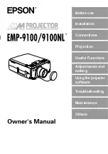
z
Complementary output
Complementary output is a method to output via two tran-
sistors.
The wiring is connected to the 0-V side when output is ON
and to the power-supply side when output is OFF.
This design does not allow the wiring to be left open (at high
impedance) as with the case of open-collector output
encoders.
Therefore, this provides a stable output from the encoder.
Pulse Train Input Type
Selection (P004) setting
RUN command
*1
*1. When both the forward RUN command and the reverse RUN command are ON or OFF, the inverter does
not start its output.
Multi-function
Input S7
Terminal EB
Recognized feedback rotation
direction
Forward Reverse
00
(Phase A and B 90°phase
difference pulse train)
ON
OFF
−
Forward
*2
*2. The inverter recognizes the rotation direction via RUN command input because it cannot recognize the ro-
tation direction by the single-phase pulse train.
However, if the RUN command is switched during operation, the inverter retains the rotation direction before
the switching until its output frequency causes a deceleration stop and then switches to the rotation direction
recognized via RUN command input.
OFF
ON
−
Reverse
*2
01
(Phase-A/B 90
°
phase dif-
ference pulse train)
Forward or
Reverse is ON
Lower than
1.8 kHz
*3
*3. For the multi-function Input S7 terminal, the maximum frequency is 1.8 kHz. Therefore, the inverter cannot
recognize the rotation direction from the Phase A and B 90°phase difference pulse train at over 1.8 kHz via
the terminal EB.
At 1.8 kHz or higher, the inverter retains the rotation direction at lower than 1.8 kHz.
Detects encoder rotation (90
°
phase dif-
ference).
1.8 kHz min.
*3
Retains rotation direction at lower than
1.8 kHz via the terminal EB.
03
(Single-phase pulse train
+
direction)
Forward or
Reverse is ON
OFF
Forward rotation (Follows terminal EB)
ON
Reverse rotation (Follows terminal EB)
6-5-2
Recommended Encoder and Its Wiring
OUT
0 V
E6C3-CWZ5GH
NPN
Transistor
PNP
Transistor
Signal
Power
Summary of Contents for SYSDRIVE MX2 SERIES
Page 1: ...Multi function Compact Inverter MX2 Series Type V1 User s Manual I585 E1 01 3G3MX2 A V1 ...
Page 32: ...CONTENTS 29 Multi function Compact Inverter 3G3MX2 V1 User s Manual I585 E1 ...
Page 108: ...2 Design 2 48 Multi function Compact Inverter 3G3MX2 V1 User s Manual I585 E1 ...
Page 176: ...4 Parameter List 4 42 Multi function Compact Inverter 3G3MX2 V1 User s Manual I585 E1 ...
Page 538: ...10 Troubleshooting 10 22 Multi function Compact Inverter 3G3MX2 V1 User s Manual I585 E1 ...
Page 598: ...12 Options 12 50 Multi function Compact Inverter 3G3MX2 V1 User s Manual I585 E1 ...
Page 614: ...Appendices A 16 Multi function Compact Inverter 3G3MX2 V1 User s Manual I585 E1 ...
Page 615: ...I 1 Multi function Compact Inverter 3G3MX2 V1 User s Manual I585 E1 I Index ...