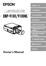
background image

Before use

Installation

Connections

Projection

Useful Functions

Adjustments and
setting

Troubleshooting

Maintenance

Others

Using the projector
software

Summary of Contents for EMP-9100

Page 1: ...Before use Installation Connections Projection Useful Functions Adjustments and setting Troubleshooting Maintenance Others Using the projector software ...

Page 2: ...trol 2AA Batteries for the remote control three cell alkaline manga nese batteries Power Cord Computer Cable Computer Cable mini D Sub 15 pin 5BNC Audio Cable RCA Audio Cable Yellow RCA Audio Cable Red White Main Cable USB Mouse Cable PS 2 Mouse Cable Serial Mouse Cable Mac Mouse Cable Mac Serial Cable PC Serial Cable Projector Soft ware CD ROM Owner s Manual this document PS 2 MOUSE E S U O M L A...

Page 3: ...resolution liquid crystal panel 1366 1024 Compact and light A compact body makes it easy for carrying around approximately 8 3Kg 18 3 litres Beautiful video images The three dimensional Y C separation and smooth motion I P conversion technology provide vivid video images DVI D port that supports digital output Fitted with a DVI D Port for digital input purposes This can also be connected to a comp...

Page 4: ...re 22 Installation example 22 Screen size and projection distance 23 Projection angles 24 Connecting the projector to a computer 25 Eligible computers 25 In the case of the mini D Sub 15 pin 27 When the monitor port is the 5BNC When connected to the second computer 28 When the monitor port is 13w3 28 In the case of 5BNC When connected to the second computer 29 In the case of DVI D 30 Sound connect...

Page 5: ...ng projection 40 Ending 43 Adjusting the Projection Position 45 Feet adjustments 45 Adjusting the Projection Size 46 Zoom adjustment 46 Trapezoid adjustment 46 Picture Quality Adjustment 47 Focus adjustment 47 Auto adjustment when projecting computer images 47 Tracking Adjustments when projecting computer images 48 Synchronization Adjustments when projecting computer images 48 Calling out adjustme...

Page 6: ...nction 56 Cursor Stamp 56 Box 56 Spotlight 57 Bar 58 Canceling effects 58 P in P Function 59 Volume Adjustment 60 Menu Configuration 61 Menu items 61 Menu Operations 63 Operation method 63 Setting items 65 User logo registration 70 Introduction of Projector Software 72 Outline of Projector Software 72 Computer Connections 73 Serial Connections 73 ...

Page 7: ...e Small 84 The image color is bad 85 The image is dark 85 No sound 86 The remote control won t work 86 Cannot end after the Power button has been pressed 87 EMP Link V will not function 87 Cleaning the Projector Cleaning the Lens Cleaning the Air Filter 88 Cleaning the projector 88 Cleaning the lens 88 Cleaning the Air Filter 89 Replacing the Air Filter 90 Replacement method 90 Replacing the Lamp ...

Page 8: ...6 Contents Terminology 97 Specifications 99 Check Sheet 100 World Wide Warranty Terms 103 Index 107 ...

Page 9: ...oint Includes supplementary explanations and useful tips Reference Indicates reference pages Refer to the terminology Usage of the terms this unit and this projector in this manual The terms this unit and this projector appear regularly in this manual and these terms also cover the accessories supplied with the projector and other optional products The projection distances illustrations and screen...

Page 10: ... may result in the outbreak of fire electric shocks or other incidents Never use an electrical voltage other than that displayed The use of a voltage other than that specified may result in the outbreak of fire or electric shocks Verify the specifications of the Power Cord The Power Cord supplied with the projector conforms to the electrical specifications of the country of purchase If the project...

Page 11: ...ojector includes many glass parts such as the lens and lamps If any of these parts should break handle them with extreme care to avoid injury and then contact your dealer or nearest Epson Service Center and request repairs Never places vases or containers that contain liquid on top of the projector If the water is spilt and enters the outer case it may result in the outbreak of fire or electric sh...

Page 12: ...oil steam or water steam such as kitchens or near humidifiers Failure to observe this may result in the outbreak of fire or electric shocks Never block the projector s suction inlets or ventilation outlets Failure to observe this may result in the build up of high temperatures inside the projector leading to the outbreak of fire Do not place the projector in the following locations In narrow badly...

Page 13: ...er use combinations of different batteries or old batteries together with new batteries Never use batteries that are not specified in the instruction manual If liquid should leak from the battery wipe up the leakage with a cloth and then replace the battery accordingly Replace the batteries immediately when the time for replacement arrives Remove the batteries when the projector is not to be used ...

Page 14: ...0C may result in damage of the case Take special care to avoid placing the equipment in direct sunlight for a long period of time Do not use the projector with the lens cover still in place The heat generated by the lens may cause the cover to become malformed The liquid crystal display panel has been manufactured with high accuracy technology and contains more than 99 99 active pixels However not...

Page 15: ...mp Indicator 2 Operation Indicator 3 Temperature Indicator 4 Handle 5 Lens Shift Knob 6 Foot Adjust Lever 7 Operation Panel 8 Speaker 9 Remote Control Receiver 10 Theft Prevention Lock see page 98 11 Focus Ring 12 Zoom Ring 13 Lens Cover 14 Front Foot 1 2 3 4 5 6 7 8 9 10 11 13 12 14 ...

Page 16: ...14 Parts Names and Operations Back Panel 1 Remote Control Receiver 2 Fan 3 Power Inlet 4 I O Port Rear Panel 1 Front Foot 2 Rear Foot 3 Air Filter suction inlet 1 2 3 4 1 2 3 ...

Page 17: ...images are being projected 8 Sync button see page 48 Makes the necessary adjustments when the screen is out of focus or flickering This button functions as the up and down key when the menu or help text are being displayed 9 Shift button see page 60 Adjusts the volume when pressed simultaneously with the Volume Keystone button 10 ESC button see page 64 Ends functions that are currently in use Retu...

Page 18: ...d is to be used when the remote control is used as a wireless mouse 7 Audio 1 Port Inputs the audio signals from the computer and A V equipment connected to the Computer 1 Port 8 S Video Port Inputs the A V equipment s S image signals 9 S Video Audio 2 Port Inputs the audio signals from the computer and A V equipment connected to the BNC port or the S Video port Outputs only the sound for connecte...

Page 19: ...ncel this mode 6 Effect button see page 56 Executes the allocated effect function Press the ESC key to cancel this mode 7 Light button The remote control button will be illuminated for approximately ten seconds 8 Power button see page 40 43 Switches the power supply to the projector on and off 9 R C ON OFF switch see page 40 44 Switches the remote control unit on and off The remote control unit ca...

Page 20: ...mizes the computer image 5 P in P button see page 59 Displays the video image within the computer image or the video image as a sub screen This function is cancelled by pressing this button once again 6 Volume button see page 60 Adjusts the volume 7 Help button see page 50 Displays the method of solving problems Press this button when trouble occurs 8 Comp2 YCbCr button see page 41 Switches betwee...

Page 21: ...Parts Names and Operations 19 Rear Panel 1 Battery Cover 1 ...

Page 22: ...istance approximately 10 meters of the remote control is diminished when signals are reflected off screens depending on the type of screen in use Ensure that sunlight and florescent lighting is not shone directly into the projector s light receiving area If the remote control will not function or malfunctions there is a possibility that the batter ies need changing In this event replace the batter...

Page 23: ...pwards 2 Insert the batteries Ensure that the batteries are aligned correctly with the and labels on the remote control 3 Replace the cover Apply pressure to the battery cover until it clicks firmly into place Point Specified batteries Two three cell alkaline manganese batteries LR6 The batteries should be replaced approximately once every three months when used for thirty minutes per day Caution ...

Page 24: ...t screens from the rear Set the rear parameter to ON see page 69 Ceiling suspension is also possible with the use of the optional ceiling suspension unit Caution Do not block the ventilation outlet at the back of the projector or the Air Filter suction inlet on the rear panel There are cases where material or paper get sucked onto the Air Filter on the rear panel when the projector is in use so at...

Page 25: ...ard lense is in use If optional lenses are to be used refer to the relevant instruction manuals for further details The screen size will become smaller when the trapezoid correction function is used Screen Size Approximate Projection Distance 30 inch 61 46cm 1 1m to 1 4m 40 inch 81 61cm 1 5m to 2 0m 60 inch 120 90cm 2 2m to 3 0m 80 inch 160 120cm 3 0m to 4 1m 100 inch 200 150cm 3 7m to 5 1m 200 in...

Page 26: ...he projection position up and down with the lens shift function When viewing from the top or bottom Point Although the projection position can be adjusted with the foot lever see page 45 there are cases where the screen will distort into a trapezoid shape In this event adjust the trap ezoid distortion with the trapezoid correction function see page 46 A B A B A B 10 Becomes 0 A B 5 Becomes 5 Upwar...

Page 27: ...ow connections or for which optional external output ports must be purchased Point Depending on the computer there are cases when it is necessary to switch the image sig nal output with the connection key etc and the settings The table shown above provides examples for certain products Refer to the computer s instruction manual for further details Condition 2 The resolution and frequency of the co...

Page 28: ...960 1366 1024 1280 960 Virtual Partial Display SXGA 43i 60 75 85 1280 1024 1366 1024 1280 1024 Virtual Partial Display SXGA 1400 1050 1328 996 1400 1050 Virtual Partial Display 1440 1080 1366 1024 1440 1080 UXGA 48i 60 65 70 75 80 85 1600 1200 1366 1024 1600 1200 Virtual Partial Display MAC13 640 480 1366 1024 640 480 MAC16 832 624 1366 1024 832 624 MAC19 1024 768 1366 1024 1024 768 MAC21 1152 870...

Page 29: ...the monitor port is the D Sub 15 pin Caution Switch off the power supply to the projector and computer before attempting to make the connection Failure to observe this may result in damage Confirm the shape of the cable connector and the shape of the port before making the con nection Applying excessive force when the direction or shape of the connector and port differ may result in defects and da...

Page 30: ...ctions with both the Computer 1 Port and the Computer 2 Port when two computers are to be connected When the monitor port is 13w3 The Computer 1 Port is also connected to the D Sub 15 port with the use of the conversion cable when the 13w3 port is used for connecting the computer s monitor port to a work station The projector s computer 1 mini d Sub 15 Port is connected to the computer s monitor p...

Page 31: ...arameter to RGB when establishing the connection see page 67 Make the connection with the 5BNC 5BNC cable available on the open market when the computer monitor port is 5BNC Connections can be made to both computer 1 port and computer 2 port when two com puters are to be connected Computer 2 BNC Port Monitor Port Computer Cable supplied with the projector Connection with the first computer Connect...

Page 32: ...computer 1 DVI D port with the optional digital video cable Select the cable in accordance with the shape of the computer port DVI D DFP Set the switch to the digital setting left hand side with the tip of a ballpoint pen or other pointed object Point There are cases where the computer must be set up in order to switch the computer output to the DVI D Refer to the instruction manual for the comput...

Page 33: ...Port stereo mini jack to the computer s audio output port with the Audio Cable supplied Connecting the computer to Computer 2 Connect the computer s audio output port to the projector s S Audio Audio 2 port RCA pin jack with the RCA audio cable sold on the open market Point The audio signals output the selected image s sound Computer Audio Output Port Audio Cable supplied with the projector Audio ...

Page 34: ...ct the projector s monitor out port to the computer monitor with the cable attached to the monitor Point There are cases where the optional Mac Desktop Adapter and Mac Monitor Adapter are required when connecting up to a Macintosh Images cannot be displayed on external monitors when the computer is connected to the DVI D port Monitor Out Port Cable attached to the monitor ...

Page 35: ... environments Only a computer mouse connected to the mouse com port can be used The mouse cannot be used when the effect function is in progress There are cases where the computer must be set up Refer to the instruction manual for the computer for further details Switch off the power to the projector and computer before making the connection It is necessary to reboot the computer if it does not wo...

Page 36: ...operations will be reversed if the left right button functions of the mouse pointer have been amended with the computer The mouse cannot be used when the Effect P in P and E Zoom functions are in use The movement speed of the mouse pointer can be changed see page 67 Power Freeze A V Mute E Zoom R C ON OFF 3 1 5 2 4 Enter Esc Power Freeze A V Mute E Zoom R C ON OFF 3 1 5 2 4 Enter Esc ENTER button ...

Page 37: ...he case of S image signals Connect the projector s S Video Port to the video equipment with the S Video cable available on the open market Connect the supplied RCA Audio Cable Red White to the S Audio Audio 2 Port if the sound is to be output from the projector s speakers Video Port yellow Audio Port white Audio Port red To the audio output port L white To the audio output port R red To the video ...

Page 38: ...onnector available on the open market is required on the projector s BNC port when a component image cable is connected Align the video with the equipment port Set the BNC parameter to CbCr when the connection has been established see page 67 Video equipment R Y Cr Y B Y Cb Projector R R Y G RCG B B Y R Cr Pr Port G Y Port B Cb Pb Port Audio port White Audio port Red To the R Y Cr output port To t...

Page 39: ...put from the projector s speakers Point Set the BNC parameter to CbCr when the connection has been established see page 67 Establishing connections with digital tuners is only possible in Japan Supports digital tuners up to the D4 rating R Cr Pr Port G Y Port B Cb Pb Port Audio Port white Audio Port red RCA Audio Cable supplied with the projector The D port cable optional for com ponent images To ...

Page 40: ...Point Purchase the component image cable so that one end matches the BCN type port on the projector and the other matches the port on the video equipment Set the BNC parameter to RGB when the connection has been established see page 67 R Cr Pr Port G Y Port B Cb Pb Port Audio Port white Audio Port red To the R output port To the G output port To the B output port RCA Audio Cable supplied with the ...

Page 41: ...ll be illuminated in orange Point Button operations are not possible when the Operation Indicator is blinking in orange Warning Never look directly into the lens once the power supply has been switched on Failure to observe this may result in the powerful light damaging eyesight Ensure that the Power Cord supplied is used The use of cables other than the one supplied may result in the outbreak of ...

Page 42: ...e Operation Indicator is blinking in orange Power Video Computer A V mute Resize Esc Help Menu Shift Keystone Volume Sync Sync T r a c k i n g T r a c k i n g Power Power Freeze A V Mute E Zoom R C ON OFF 3 1 5 2 4 Enter Esc Power Set the R C ON OFF switch to ON first of all when using the remote control unit A message stating No image signals input will be displayed when no image signals have bee...

Page 43: ... Video on the main unit and Comp2 YcbCR on the remote control can only display either BNC RGB or BNC YcbCr depending on the BNC setting see page 67 Connected Port Button to Select Display at the top right hand corner of the screen Main Unit Remote Control Computer 1 Port Computer will change when ever pressed Comp1 Computer1 BNC Port RGB BNC RGB BNC Port YCbCr Video will change when ever pressed C...

Page 44: ...he settings after establishing the connec tion The table shown above provides examples for certain products Refer to the computer s instruction manual for further details Press the Resize button when signals that support DVD players or wide television screens 16 9 images have been input The parameters will change between 4 3 images and 16 9 images whenever the switch is pressed There are cases whe...

Page 45: ...he message will be erased after seven seconds if no buttons are pressed the power will remain on It is also possible to end projection by pressing the Power button as explained in proce dure 1 for more than one second will assume the same status as if ending with proce dure 2 Button operations are not possible when the Operation Indicator is blinking in orange In this event please wait until full ...

Page 46: ...OFF when not in use 5 Restore the Front Foot if it has been extended Steady the projector by hand and then lift the Foot Adjust Lever with a finger and gently lower it into the main Unit 6 Attach the lens cover Caution Do not remove the Power Plug from the socket when the Operation Indicator is blinking in orange Failure to observe this may result in damage to the equipment and will speed up the p...

Page 47: ...raise the front part of the projector The Front Foot will protrude 2 Remove your finger from the Foot Adjust Lever and then let go of the projector 3 Rotate the lower part of the Front Foot to minutely adjust the height Point There are cases where the screen will be distorted into a trapezoid shape when foot adjustments are performed This trapezoid distortion can be adjusted with the use of the tr...

Page 48: ...orted into a trapezoid with foot adjustment 1 Press the Keystone button to lengthen the screen sidewards Point The screen will be reduced in size when trapezoid correction has been performed The status of trapezoid correction will be recorded Perform readjustments that match the installation position when the projection position or angle have been changed Reduce the sharpness if blurring occurs af...

Page 49: ...computer images Automatically adjusts the computer image to attain the optimum effect The items adjusted include the Tracking Position and Sync 1 Press the Enter button on the projector the Auto Capture button on the remote control Point If auto adjustments are initiated when the E Zoom A V Mute or P in P functions are exe cuting adjustment will not be carried out until the executing function has ...

Page 50: ...equence whenever this button is pressed Point There are cases when these adjustments must be made again if the values output from the computer resolution display color are amended after flashing and blurring have been adjusted There are cases where flashing and blurring is caused by adjusting the brightness and contrast Images will be projected more vividly if synchronization adjustments are made ...

Page 51: ...e size of the image Resize Resize 53 E Zoom Enlarges the image Zoom 55 Effect Adds decorations to the image Effect 56 P in P Adds a sub screen to the image P in P 59 Preset Calls out pre registered adjustment val ues Preset Preset 48 Trapezoid correction Corrects trapezoid correction Keystone 46 Auto adjustment Automatically adjusts the image for optimum effect Enter Auto 47 Tracking Adjusts verti...

Page 52: ...e item by pressing the Enter button on the main unit the Enter button on the remote control unit Help Esc Menu Comp1 P in P Preset Video Comp2 BNC Help Volume Auto Resize Power Video A V mute Resize Esc Help Menu Shift Keystone Volume Sync Sync T r a c k i n g T r a c k i n g Help Computer HELP Menu Help for the image Help for the sound Language selection Language If you follow the instructions to...

Page 53: ... solve your problems see page 78 The help menu can be canceled by pressing the ESC or Help buttons HELP Menu An image does not appear on the Screen The image is not in focus The image is blurred The image is not displayed fully on the Screen cut off too big too small partial The colors of the image are not correct The image is too dark The image is trapezoid Select Return Enter Exit ...

Page 54: ...n tempo rarily erasing images and sound see page 67 Point The Epson logo has been registered in the user logo User logo registration and setup is necessary to amend the user logo see page 68 Freeze Function Temporarily freezes the image however the sound will not be muted 1 Press the Freeze button The image will freeze Press the Freeze button once more to cancel this mode Power Video A V mute Resi...

Page 55: ...ire size of the projection Example In the case of 800 x 600 Example In the case of 1600 x 1200 Point The size will not be switched if the display resolution of the liquid crystal is the same as the entered resolution 1024 x 768 dots A certain portion of the image will not be displayed if the entered resolution is larger than the display resolution of the liquid crystal Lower the Enter button on th...

Page 56: ...g Image Sizes In the case of video images Switching will be performed for 4 3 and 16 9 image sizes Images recorded with digital videos and DVD images can be projected on 16 9 wide screens 4 3 display 16 9 display ...

Page 57: ...duced or enlarged The size percentage will be displayed Point Enlargement is possible with 24 stages between 1x and 4x at increments of 0 125x A certain portion of the image will not be displayed when it has been enlarged Lower the Enter button on the remote control to scroll the screen and display this portion accord ingly Sub screens will be enlarged when the P in P function is being used E Zoom...

Page 58: ...it to move the position of the cursor stamp 3 The stamp will be imprinted at the location of the cursor when the Enter button on the remote control unit has been pressed Point The efect function will be canceled and the cursor will disappear when the Esc button is pressed The decoration will be erased when the 5 button is pressed The mouse cannot be used when the effect function is in progress Box...

Page 59: ...fficult to see depending on the color combina tion of the image s background and four corners Amend the color of the corners in this event see page 66 The mouse cannot be used when the effect function is in progress Spotlight Shines a spotlight on a certain part of the image 1 Press the 3 button Will switch between three different spotlight sizes whenever the 3 button is pressed 2 Lower the Enter ...

Page 60: ...sition Point The effect function will be canceled and the bar will disappear when the Esc button is pressed There are cases where the effect will be difficult to see depending on the color combina tion of the image s background and the bar Amend the color of the bar in this event see page 67 The mouse cannot be used when the effect function is in progress Canceling effects 1 Press the 5 button The...

Page 61: ...o sub screen sound Press the 2 button to return to the main screen sound after the sound has been switched 5 Press the Enter button to set the sub screen display The operation guide in the bottom left hand corner will be erased Point The sub screen will be erased when the PinP button is pressed again The computer image or video image will be displayed in the main screen and the video image Video S...

Page 62: ... pressing the Shift button Volume button on the remote control Point Adjustment is not possible when no sound signals are being input Power Video Computer A V mute Resize Esc Help Menu Shift Keystone Volume Keystone Volume Sync Sync T r a c k i n g T r a c k i n g Shift Esc Menu Comp1 P in P Preset Video Help Volume Volume Comp2 YCbCr Auto Resize ...

Page 63: ...cking Sync Brightness Contrast Sharpness Gamma Resolution Preset Reset Adjustment Select Execute 9999 99 0 0 0 Auto Normal Dynamic Natural Manual Select Top menus Sub menus image Position Tracking Sync Brightness Contrast Sharpness Gamma Resolution Preset Reset Adjustment Select Execute 9999 99 0 0 0 Video Audio Effect Setting Capture Advanced About Reset All Auto Normal Dynamic Natural Manual Sel...

Page 64: ...al Msg Prompt A V Mute BNC DPMS Reset Execute 0 OFF Black ON OFF Blue Black Blue RGB YCbCr ON OFF Logo Logo Composite S Video Video Audio Effect Setting Capture Advanced About Reset All Select Enter User s Logo Capture Execute Video Audio Effect Setting Capture Advanced About Reset All Select Enter Language Startup Screen Color Setting Comp2Sync Termination Rear Proj Ceiling Reset Select English E...

Page 65: ...displayed 4 Then select the detailed sub item Press the Sync button on the projector lower the Enter button up or down on the remote control unit to select the sub item The items displayed on the image menu and information menu will differ in accordance with the projected input source Power Video A V mute Resize Esc Help Menu Shift Keystone Volume Sync Sync T r a c k i n g T r a c k i n g Menu Com...

Page 66: ... the other items in the same way 7 Press the Menu button The menu will end Point Press the ESC button to return to the previous menu in the hierarchy The items displayed on the image menu will differ in accordance with the projected input source and menus other than that belonging to the projected input source cannot be adjusted Image menus cannot be adjusted when no image signals are being input ...

Page 67: ...of the image Dynamic Produces an image with clear color differences Suitable for displaying plans etc Normal Projects tint without correction Natural Produces an image with natural tint Suitable for video images Normal Resolution Sets the input resolution Auto Automatically adjusts the input resolution Manual Press the Enter button and select the required set ting from the input resolution selecti...

Page 68: ... all image and sound values to the default settings see page 69 Effect Cursor Stamp Sets the shape size color and length of the cursor stamps allocated to the 1 button Press the Enter button and select the item to be displayed from the cursor stamp setup menu The shape size color and length conditions can be set by pressing button types 1 to 3 respectively depending on the selected cursor shape si...

Page 69: ...educed in size when trapezoid correction has been performed The status of trapezoid correction will be recorded Perform readjustments that match the installation position when the projection position or angle have been changed Reduce the sharpness if blurring occurs after trapezoid correction see page 65 Center value P in P Sets the input source for the P in P function s sub screen The P in P func...

Page 70: ...complete Do not attempt to operate the projector or the equipment connected to the projector while this procedure is running Failure to observe this may result in damage The size that can be registered is 400 x 300 dots The display size will be adjusted when video images are being projected Not registered Adva nced Language Sets the language with which messages are to be displayed Press the Enter ...

Page 71: ... be be inverted from left to right and up and down The optional ceiling suspension unit is required to suspend the projector from the ceiling see page 94 OFF Reset Returns all advanced setting menu adjustment values to the default values Press the Enter button and then select Yes on the confir mation screen displayed Select Reset All to return all image and sound values to the default settings Inf...

Page 72: ...e Enter button on the main unit the Enter button on the remote control The image to be registered will be displayed 4 Adjust the position of the image and then press the Enter button on the main unit the Enter button on the remote control The confirmation screen will be displayed User s Logo Capture Execute Video Audio Effect Setting Capture Advanced About Reset All Select Enter User s Logo Captur...

Page 73: ...it until the saving completed screen is displayed Point A certain amount of time is required for the saving process Do not operate the projector or connected equipment while saving is in progress Failure to observe this may result in defects The image size that can be registered is 400 x 300 dots The display size will be amended when the video image is being projected User s Logo Capture Do you us...

Page 74: ...following Outline of Projector Software The various types of Projector Software available are explained below EMP Link V Enables the projector settings to be amended from the computer This allows functions to be allocated to the Effect button and user logos to be edited refer to the EMP Link V Users Guide PDF ...

Page 75: ...port see page 25 Switch on the projector and ensure that the connection has been set up before using the software Windows Computers Connect the projector s Mouse Com Port to the computer s serial port with the use of the PC Serial Cable and Main Cable supplied Caution Ensure that the power supply to the projector has been switched off before attempting to establish the connection Failure to observ...

Page 76: ...tor s Mouse Com Port to the computer s printer port or modem port with the use of the Mac Serial Cable and main cable supplied MAC SERIAL Mouse Com Port Main Cable supplied with the projector Mac Serial Cable supplied with the projector Printer port or Modem port ...

Page 77: ... V computers operating on the Windows 95 98 NT4 0 2000 platform CPU Pentium133MHz or more Available memory capacity 32MByte or more an additional 8MBytes when operating the Acrobat Reader Available hard disk capacity EMP Link V EMP Link PDF User s Guide 5MByte or more Acrobat Reader 10MByte or more Display Resolution of 16bit High Color 640x480 or more Macintosh Operable computer Operating on Appl...

Page 78: ...s 1 Start up Windows and set the CD ROM in place The set up program will start automatically Point If the set up program does not start automatically open the Specify and execute file name dialog box from the Start Specify and execute file name menu and enter CD ROM drive name SETUP 2 Select the language and the program to be installed and then press the OK button Installation will then commence P...

Page 79: ...on Proceed with all subsequent screens in accordance with the instructions provided Point Drag the EMP LinkV folder and EMP LinkV contained in System Default Settings into the trash can to un install the program Reading the User s Guide In the case of Windows Select Start Programs EMP Link V User s Guide to open the file In the case of the Macintosh Double click on the User s Guide icon contained ...

Page 80: ...oling the lamp will depend on the external temperature etc The Power button cannot be used during the cool down period This will be illuminated in orange once the cool down process has been completed so press the button once more then 46 Illuminated in Green Projection in progress Not an error 40 Blinking in Green Warm up in progress Not an error Wait for a moment The amount of time required for t...

Page 81: ...pare a new lamp It is recommended that the lamp is replaced as soon as possible as there are cases where the time for replacement is earlier than stated in the conditions of usage 91 Extinguished Not an error The power has not been switched on or nor mal projection is in progress Indicator Status Cause Recovery and Status Reference Page Illuminated in Red Excesive internal temperature overheating ...

Page 82: ...is is not an error but the projector will automatically cease operating if the tempera ture increases any further Use the projector within the permissible temperature range of between 5 degrees Celsius and 40 degrees Celsius Install the projector in a well ventilated place and ensure that the ventilation inlet and outlet are not blocked 22 Clean the Air Filter 89 Extinguished Not an error The powe...

Page 83: ...tton will work again after the cooling down process Projection lamp cooling operations the operation indicator is illuminated in orange has been completed see page 46 Is the Sleep Mode set at ON When the sleep mode has been set at ON the lamp will be automatically extinguished if no operations occur and no signals are input for a period of thirty minutes see page 68 Did you press the Power button ...

Page 84: ... projector Comp1 Comp2 YCbCr Video on the remote control to switch the image see page 41 Has the power supply to the connected computer or video equipment been switched on see page 42 Are image signals being output from the connected computer or video equipment Note type and liquid crystal type computers must output image signals to the projector Image signals are not output externally simply beca...

Page 85: ...when the projector is suddenly brought into a warm room from a cold room and this may lead to the image seeming blurred In this event switch the power off and leave the unit to stand for a while Has the Sync Tracking and Position been adjusted The image can be adjusted by regulating the Tracking and Sync buttons on the projector while monitoring the image on screen Adjustments can also be made by ...

Page 86: ...Set the signal format with Menu Image Resolution There are cases where the image signals being input cannot be determined in the Auto mode see page 65 In the case of video images Select the video signal format with Menu Image Video Signal Format There are cases where the video image signals being input cannot be determined in the Auto mode see page 66 The image is cut up The image is small There i...

Page 87: ...normality see page 65 Is it time to replace the lamp If the Lamp Indicator is blinking it means that the time to replace the lamp is drawing near When the time to replace the lamp draws near the image will appear dark and the tint will deteriorate In this event replace the lamp with a new one see page 91 Is it time to replace the lamp If the Lamp Indicator is blinking it means that the time to rep...

Page 88: ... see page 40 Is the remote control being aimed in the correct direction The operable range of the remote control unit is 30 to the left and right and 15 up and down see page 20 Is the distance between the remote control and the projector too great The operable distance of the remote control unit is approximately 10m see page 20 Is the remote control receiver connected and the remote control being ...

Page 89: ...l down process to allow the projector lamp to cool down the operation indicator will blink in orange will be performed after the power has been switch off by pressing the Power button The operation indicator will be illuminated in orange when this has been completed so remove the power plug from the socket at this point The amount of time required for the cool down process will depend on the exter...

Page 90: ...nything other than soft materials Warning Personnel other than qualified servicemen must never open the projector Many high volt age parts are contained inside the cover that may cause electric shocks Contact your dealer or your nearest adress provided at page 104 to request internal inspections repairs adjust ments cleaning and other tasks Exercise caution when handling the Power Plug and Power C...

Page 91: ...ay result in damage Ensure that the projector is stood on its end and the Air Filter cleaned with a vacuum cleaner to prevent the dirt and dust from penetrating inside Point If it is no longer possible to remove the dirt from the Air Filter or it begins to crack it is time to replace it Contact your dealer in this event A replacement air filter is packaged with the replacement lamp Replace the Air...

Page 92: ...e amount of time required for the projector to cool down will depend on the surround ing temperature 2 Remove the Air Filter Point Ensure that the projector is stood on its end when replacing the Air Filter to prevent the dirt and dust from penetrating inside 3 Set a new Air Filter in place Point Insert the clips before pressing on the catch to set the air filter in place ...

Page 93: ...in the initial brightness levels and picture quality The replacement message has been set at approximately 2 000 hours of use in order to maintain the initial brightness levels and picture quality Although the replacement message is displayed after approximately 2 000 of use there are cases where the individual characteristics of each lamp and other usage conditions result in it not lighting up be...

Page 94: ...ture 2 Once the projector has cooled down sufficiently remove the Fan Approximately sixty minutes are required for the projector to cool down sufficiently Remove the two screws holding the Fan in place 3 Withdraw the lamp Loosen the three screws holding the lamp in place and then pull the lamp out towards you 4 Attach a new lamp Align the direction push the lamp in as far as it will go and then se...

Page 95: ...ccordance with the following procedure after the lamp has been replaced with a new one Resetting the lamp illumination time 1 Press the Help button for five or more consecutive seconds The screen for resetting the lamp s illumination time will be displayed after the help menu has been displayed 2 Select Yes Press the Tracking on the main unit lower the Enter button on the remote control unit and s...

Page 96: ...nch Screen ELPSC07 80 inch Screen ELPSC08 Portable Screen ELPSC06 50 inch Dual Stacker ELPMB04 Ceiling Plate ELPFC03 Used to adjust the height of the ceiling mount Ceiling Mount ELPMB06 Silver Used for attaching the projector to the ceiling Pipe 370 ELPFP01 Black ELPFP04 Silver 570 ELPFP02 Black ELPFP05 Silver 770 ELPFP03 Black ELPFP06 Silver Ceiling Bracket ELPFC02 Used when the stacker is to be ...

Page 97: ...rried on board aircraft as cabin baggage Computer Cable Used when connecting a computer to the projector Mini D Sub 15pin Mini D Sub 15 pin ELPKC 02 1 8 m Same as the one supplied ELPKC 09 3 0m Digital Video Cable Use this cable when connecting a computer which can output digital signals to this unit s digital port Monitor adapter Desktop adapter DVI D DVI D ELPKC20 3 0m DVI D DFP ELPKC21 3 0m ...

Page 98: ...nt impact and then place it in a strong cardboard box for transportation purposes When transporting repeatedely Place the projector in the optional Hard Travel Case ELPKS15 and clearly mark that it is a precision instrument for the delivery people and then request transportation It is recommended that the Handle With Care stickers are attached to the Hard Travel Case during transportation When car...

Page 99: ...gned with the frequency of the projector Aligning the signal phasing is known as synchronization Projected images will be subject to distrubance blurring and horizontal noise if not syn chronized VGA IBM PC AT compatible DOS V equipment signals with 640 horizontal pix els and 480 vertical pixels XGA IBM PC AT compatible DOS V equipment signals with 1 024 horizontal pixels and 768 vertical pixels U...

Page 100: ...he open market is passed through the holes on the projector case to secure it to a desk or column These holes sup port the Micro Saver Security System manufactuered by Kensington Inc The agency for this product within Japan is listed below Japan Poloroid Inc Electronic Images Division 30th Mori Bldg 3 2 2 Toranomon Minato ku Tokyo 105 8456 Tel 03 3438 8879 Fax 03 5473 1630 Synchronization Sync Out...

Page 101: ...wer saving 100 120VAC 50 60Hz 4A 200 240VAC 50 60Hz 2A Temperature range during use 5 40 with no condensation Temperature range during storage 10 60 with no condensation Weight Approximately 8 3kg Connection ports Computer 1 port Single system mini D Sub 15pin female DVI D port port switch Monitor Out port Single system mini D Sub 15pin female Audio 1 port for use with Computer 1 S Audio Audio2 po...

Page 102: ...etup Sleep Mode ON Information computer Lamp ON Time H Frequency H Hz SYNC polarity SYNC mode Separate Composite Input resolution X Refresh sheet Hz Information video Lamp ON Time H Video signal system H Positive Negative V Positive Negative AUTO NTSC Others Sync on Green Describe the problem EMP Serial number Purchasing time Year month Indicator Describe the color of the indicator lamps and the s...

Page 103: ... equipment Video DVD camera Manufacturer s name Model Audio cable A V cable Specially designed Length m Model number Wiring additional equipment Model number Switching unit Model number Sound input connector Is it plugged in firmly Stereo mini video Audio1 Computer1 Audio2 Computer2 RCA pin S Composite Image input connector Computer Computer1 Computer2 BNC Video S Composite Component BNC Time of o...

Page 104: ...omputer Connector Computer1 Computer2 BNC Mouse Com Is a cable connected to the remote control connector Connector Is it plugged in firmly Mouse PS 2 Serial mouse USB ADB 98 NEC Serial when EMP Link is in use Main mouse cable Specially designed Length m Model number Switching unit Model number Time of occurrence Before use Immediately after the start of usage During usage Other Frequency of occurr...

Page 105: ...son or a service organization stipulated by Epson in countries listed in the instruction manual The period of warranty is twelve months from the date of purchase The warranty will cover the cost of spare parts and labor in accordance with the conditions laid out by Epson within the applicable range of the warranty The user will not be supplied with a substitute product during the period of repair ...

Page 106: ...ter BeNeLux Tech Help Desk 043 3515752 Web Address http www epson nl NORWAY Tech Help Desk 800 11828 CROATIA Recro d d Trg Sportova 11 HR 10000 Zagreb Tel 00385 1 6350 777 Fax 00385 1 6350 716 E mail recro recro hr Web Address http www recro hr GREECE Pouliadis Ass Corp Aristotelous St 3 GR 19674 Athens Tel 0030 1 9242072 Fax 0030 1 9441066 POLAND FOR EVER Sp z o o Ul Frankciska Kawy 44 PL 01 496 ...

Page 107: ...b Address http www epson uk SPAIN EPSON IBERICA S A Avda Roma 18 26 E 08290 Cerdanyola del Vallès Barcelona SPAIN Centro At al Cliente 902 404142 E mail soporte epson es Web Address http www epson es TURKEY Romar Pazarlama Sanayi ve TIC A S Rihtim Cad No 201 Tahir Han TR Karaköy Istanbul Tel 0090 212 2520809 Fax 0090 212 2580804 YUGOSLAVIA BS Procesor d o o Hadzi Nikole Zivkovica 2 11000 Beograd T...

Page 108: ...7 AUSTRALIA Tel 1300 361 054 Web Address http www epson com au KOREA EPSON KOREA CO LTD 17F HANSOL Bldg 736 1 Yaoksam dong Kangnam gu Seoul 135 080 KOREA Tel 2 553 3515 Fax 2 5584271 http www epson co kr SINGAPORE EPSON SINGAPORE PTE LTD 401 Commonwealth Drive 01 01 Haw Par Technocentre SINGAPORE 149598 Tel 4722822 Fax 4726408 HONGKONG EPSON Technical Support Centre Information Centre Rooms 4706 4...

Page 109: ...the Air Filter 86 Color 63 color differential 34 Color Setting 66 color temperature 66 Commencing projection 38 Comp1 button 39 Comp2 Sync Termination 67 Comp2 YCbCr button 39 component 34 composite image signals 33 Computer 39 Computer 1 DVI D Port 14 Computer 1 mini D Sub 15 Port 14 25 Computer 2 BNC Port 14 27 computer 2 BNC port 35 Computer button 13 Connecting external monitors 30 Connecting ...

Page 110: ...ne 65 Keystone button 13 L Lamp Indicator 11 77 Language 66 L Audio R Port 14 L Audio R ports 33 Left click 32 Lens Cover 11 37 lens cover 42 Lens Shift Knob 11 Light button 15 M main screen 57 Maximum Sound Output 97 Menu button 13 61 Menu Configuration 59 Menu Operations 61 mini D Sub 15 pin 25 Monitor Out Port 14 Mouse Com Port 14 31 N No Signal Msg 65 O Operable distance 18 Operable range 18 O...

Page 111: ...ton 13 Sleep Mode 66 79 Smooth Motion 63 Sound 64 Sound connection 29 Sound menu 60 Speaker 11 Specifications 97 Spotlight 55 64 SRS Center 64 SRS Space 64 Stack Out Port 14 Stamp 54 Startup Screen 66 sub menus 59 sub screen 57 S Video Port 14 33 S Video Audio 2 Port 14 Symbol displays 5 Sync button 13 Sync 63 Synchronization 46 T Temperature Indicator 11 77 temperature range 10 Temperature range ...

Page 112: ...110 Index Window resizing 51 World Wide Warranty Terms 101 Z Zoom 44 Zoom Ring 11 ...

Page 113: ...ano ken 392 8502 Japan Representative EPSON EUROPE B V Address Entrada 701 1096 EJ AMSTERDAM The Netherlands Declares that the Product Kind of Equipment LCD Projector Model ELP 9100 9100NL EMP 9100 9100NL Conforms to the following Directives and Norm s Directive 89 336 EEC EN 55022 EN 55024 EN61000 3 2 EN61000 3 3 Directive 73 23 EEC EN 60950 ...

Page 114: ...device Each product marketed is identi cal to the representative unit tested and found to be com pliant with the standards Records maintained continue to reflect the equipment being produced can be expected to be within the variation accepted due to quantity produc tion and testing on a statistical basis as required by 47CFR 2 909 Operation is subject to the following two conditions 1 this device ...

Page 115: ...rent from that to which the receiver is connected Consult the dealer or an experienced radio TV technician for help WARNING The connection of a non shielded equipment interface cable to this equipment will invalidate the FCC Certification or Declaration of this device and may cause interference levels which exceed the limits established by the FCC for this equipment It is the responsibility of the...

Page 116: ...ations to this product or excluding the U S failure to strictly comply with SEIKO EPSON CORPORATION s operating and maintenance instructions SEIKO EPSON CORPORATION shall not be liable against any damages or problems arising from the use of any options or any consumable products other than those designated as Original EPSON Products or EPSON Approved Products by SEIKO EPSON CORPORATION EPSON is a ...

Page 117: ...Printed in Japan 9001005 ...

Reviews: