


7 - 45
7 Other Functions
Multi-function Compact Inverter 3G3MX2-V1 User’s Manual (I585-E1)
7-
5 O
the
r O
p
era
tion
Fu
nct
ion
s
7
7-5
-12 PID F
unction
Precautions for Correct Use
• When the PID function is enabled, the setting unit for the following parameters is changed to
percentage as 100% of the maximum frequency.
Note also that, these parameters are read or written via Modbus communication, the data
unit differs between read and write operations. Set parameter values in units of 0.01 Hz for
writing and in units of the following percentages as 100% of the maximum frequency for
reading.
F001: 0.01%
A011, A012, A020/A220, A021 to A035, A101, A102, A145: 0.1%
• When using the PID function, do not set the Analog Input Filter (A016) to 31 (500-ms filter
with
±
0.1-Hz hysteresis). Doing so may result in unstable operation.
A157
PID Sleep Operation
Delay Time
0.0 to 25.5
Set the delay time until the sleep operation
starts.
0.0
s
C044
PID Deviation Excessive
Level
0.0 to 100.0
OD signal output judgment level
3.0
%
C052
Feedback Comparison
Signal Off Level
0.0 to 100.0
FBV signal output judgment level
100.0
%
C053
Feedback Comparison
Signal On Level
0.0 to 100.0
FBV signal output judgment level
0.0
%
C001 to
C007
Multi-function Input S1 to
S7 Selection
23:
PID (PID disabled)
−
−
24:
PIDC (PID integral reset)
C021, C022
C026
Multi-function Output
P1/P2 Selection
Multi-function Relay Out-
put (MA, MB) Function
Selection
04:
OD (Excessive PID deviation)
−
−
31:
FBV (PID feedback comparison
signal)
Related functions
A001, A201, A005, d004
*1. Setting the PID Selection (A071) to Enabled causes the analog input selection setting in A036 to be allocated
to the PID feedback function.
When the 1st Frequency Reference Selection (A001) is set to 01 (Control circuit terminal block), the analog
input setting other than that selected in A076 is used as the target frequency reference. In this case, the setting
in A005 and the function allocated to the terminal AT (Analog input switching) are disabled.
*2. Refer to
7-5-7 Frequency Calculation Function
on page 7-39.
*3. In A079, you can set a target value, or have a setting that overlaps with the PID Feedback Selection value.
With an overlapping setting, the analog input is used for both the feedback and feedforward signals.
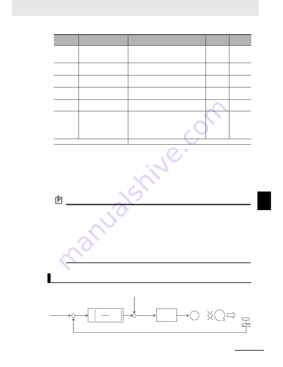
Basic Structure of PID Control
Parameter
No.
Function name
Data
Default
data
Unit
fs
M
+
−
+
−
s
Td
s
Ti
Kp
1
1 +
·
+
·
=
Disabled
Feedforward
0 to 10 V
4 to 20 mA
Target
value
Devia-
tion
ε
Feedback
Control
Normal control
of inverter
Transducer
Sensor
Kp: Proportional gain
(A072: PID P gain)
Ti: Integral time
(A073: PID I gain)
Td: Derivative time
(A074: PID D gain)
s: Operator
0 to 10 V
4 to 20 mA
0 to 10 V
4 to 20 mA
Summary of Contents for SYSDRIVE MX2 SERIES
Page 1: ...Multi function Compact Inverter MX2 Series Type V1 User s Manual I585 E1 01 3G3MX2 A V1 ...
Page 32: ...CONTENTS 29 Multi function Compact Inverter 3G3MX2 V1 User s Manual I585 E1 ...
Page 108: ...2 Design 2 48 Multi function Compact Inverter 3G3MX2 V1 User s Manual I585 E1 ...
Page 176: ...4 Parameter List 4 42 Multi function Compact Inverter 3G3MX2 V1 User s Manual I585 E1 ...
Page 538: ...10 Troubleshooting 10 22 Multi function Compact Inverter 3G3MX2 V1 User s Manual I585 E1 ...
Page 598: ...12 Options 12 50 Multi function Compact Inverter 3G3MX2 V1 User s Manual I585 E1 ...
Page 614: ...Appendices A 16 Multi function Compact Inverter 3G3MX2 V1 User s Manual I585 E1 ...
Page 615: ...I 1 Multi function Compact Inverter 3G3MX2 V1 User s Manual I585 E1 I Index ...


