


7 Other Functions
7 - 94
Multi-function Compact Inverter 3G3MX2-V1 User’s Manual (I585-E1)
Use this method to control DC injection braking according to the ON/OFF status of the RUN command.
Set the DC Injection Braking Selection (A051) to 01 (Enabled).
• To enable the DC injection braking function during startup, set the time during which DC injection
braking is applied in the Startup DC Injection Braking Power (A057) and the time during which DC
injection braking is applied in the Startup DC Injection Braking Time (A058).
• To enable the DC injection braking function during stop, set the braking power in the DC Injection
Braking Power (A054), the frequency at which to start DC injection braking in the DC Injection Brak-
ing Frequency (A052), and the time during which DC injection braking is applied in the DC Injection
Braking Time (A055).
• When the DC Injection Braking Delay Time (A053) is set, the inverter shuts off its output after the fre-
quency reaches the stop frequency value set in A052 and remains in a free-run state during the time
set in A053. After the expiration of the time set in A053, the inverter starts DC injection braking.
(Examples 5-a and 5-b)
When A053 is set to 0.0, DC injection braking works after the inverter reaches the frequency set in
A052. (Examples 6-a and 6-b)
• In the DC Injection Braking Edge/Level Selection (A056), you can set the priority between the DC
injection braking time and the RUN command input. Select optimal operation according to your sys-
tem, with reference to the example below.
However, DC injection braking during startup works independently of the DC Injection Braking
Edge/Level Selection setting. (Examples 4-a and 4-b)
Controlling DC Injection Braking via Parameter Settings (A051 = 01)
Edge operation
: The inverter gives priority to the DC Injection Braking Time (A055) and performs DC
injection braking according to the time set in A055.
Once the RUN command (FW) turns OFF, the inverter applies DC injection braking
for the time set in A055 when the output frequency reaches the value set in A052.
Even if the RUN command is turned ON while DC injection braking is active, the
inverter continues to apply DC injection braking during the time set in A055. (Exam-
ples 5-a and 6-a)
Level operation : Giving priority to the RUN command, the inverter ignores the DC Injection Braking
Time (A055) setting and shifts to normal operation.
If the RUN command turns ON while DC injection braking is active, the inverter
returns to normal operation, ignoring the time set in A055. (Examples 5-b and 6-b)
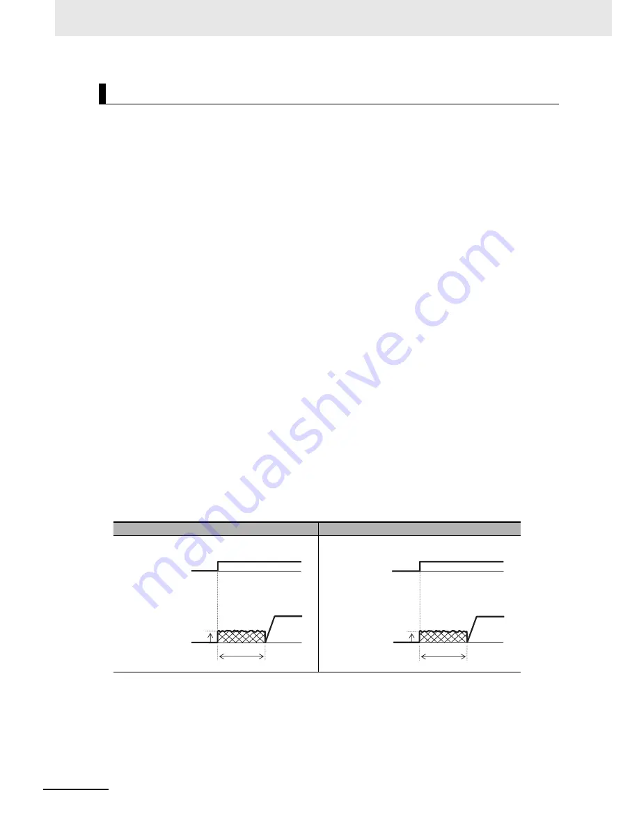
(a) Edge operation (A056 = 00)
(b) Level operation (A056 = 01)
Example 4-a. During startup
Example 4-b. During startup
A058
A057
FW input
Output
frequency
A057
A058
FW input
Output
frequency
Summary of Contents for SYSDRIVE MX2 SERIES
Page 1: ...Multi function Compact Inverter MX2 Series Type V1 User s Manual I585 E1 01 3G3MX2 A V1 ...
Page 32: ...CONTENTS 29 Multi function Compact Inverter 3G3MX2 V1 User s Manual I585 E1 ...
Page 108: ...2 Design 2 48 Multi function Compact Inverter 3G3MX2 V1 User s Manual I585 E1 ...
Page 176: ...4 Parameter List 4 42 Multi function Compact Inverter 3G3MX2 V1 User s Manual I585 E1 ...
Page 538: ...10 Troubleshooting 10 22 Multi function Compact Inverter 3G3MX2 V1 User s Manual I585 E1 ...
Page 598: ...12 Options 12 50 Multi function Compact Inverter 3G3MX2 V1 User s Manual I585 E1 ...
Page 614: ...Appendices A 16 Multi function Compact Inverter 3G3MX2 V1 User s Manual I585 E1 ...
Page 615: ...I 1 Multi function Compact Inverter 3G3MX2 V1 User s Manual I585 E1 I Index ...


