


6 - 35
6 Vector Control and Applied Functions
Multi-function Compact Inverter 3G3MX2-V1 User’s Manual (I585-E1)
6
-7 Sim
p
le Pos
ition
Co
ntro
l
6
6-
7-3 Simple
P
o
sition
Contro
l Opera
tion an
d Setting
s
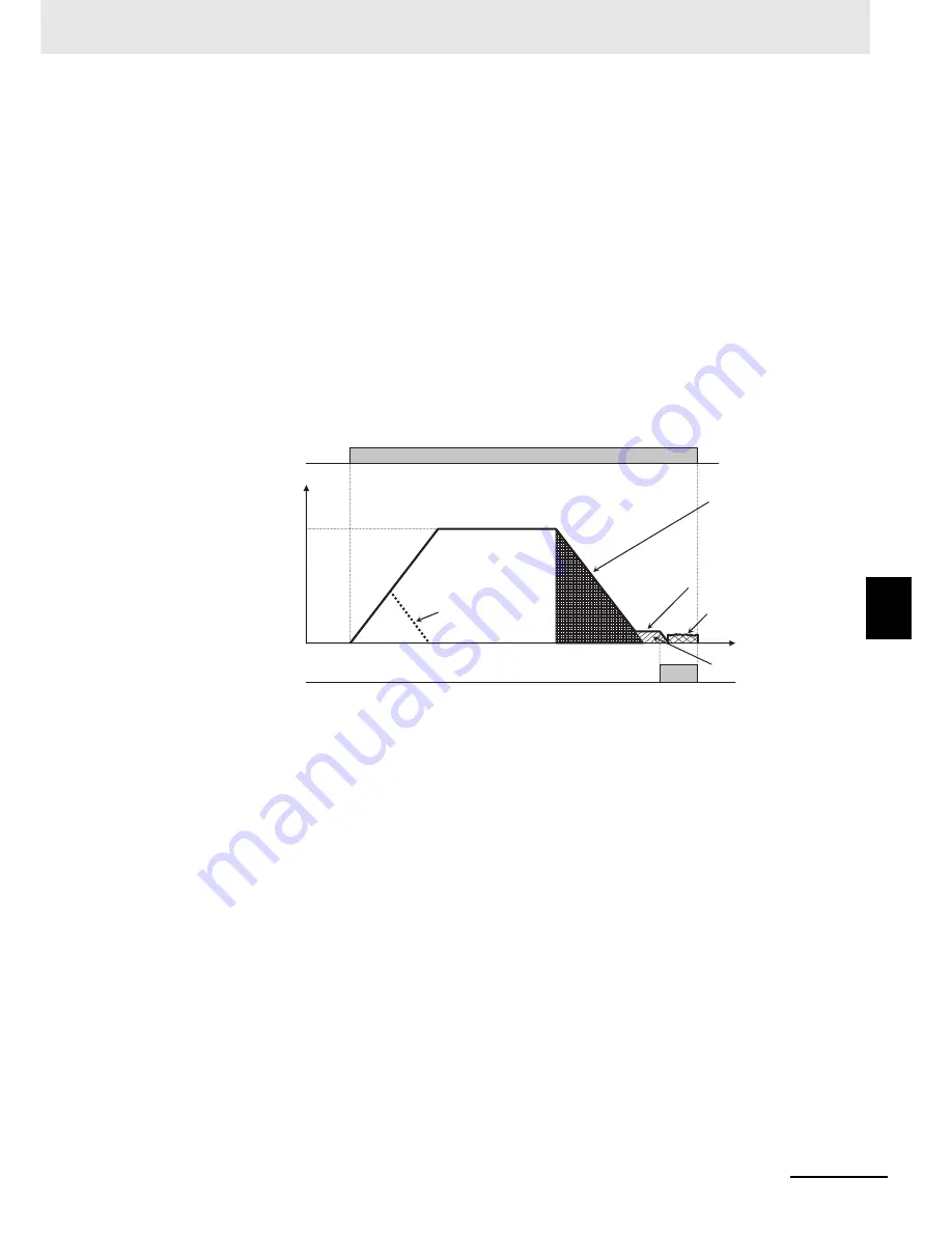
(4) The inverter starts decelerating when the motor reaches the position short of the tar-
get position by the sum of the amount of decelerating movement for the accelera-
tion/deceleration set time and the Creep Speed Moving Amount (P014).
(5) When the frequency set in the Creep Speed Setting (P015) is reached during deceler-
ation, the motor moves at the creep speed.
(6) When the motor reaches the position set in the Positioning Completion Range Set-
ting (P017) from the target position, the inverter outputs the positioning completion
signal (C021, C022, C026 = 23: POK) and decelerates according to the accelera-
tion/deceleration time settings.
(7) After the motor stops, the output status of the inverter switches to DC injection brak-
ing. The DC injection braking mode is reset when the RUN command turns OFF.
Note that this DC injection braking after stop causes the motor to move out of the stop posi-
tion due to external force because it has no position retention mechanism. If position reten-
tion is required, use external braking.
If using external braking to enable position retention, turn OFF the RUN command to
release the DC injection braking mode.
z
Precautions for use of single-phase pulse position control (P004 = 00)
When Pulse Train Input Type Selection (P004) is set to 00 (Single-phase pulse input), the direction
of motor rotation is judged based on RUN command input.
• If the motor rotates from a stop state where the RUN command is not input, the Current Position
Monitor does not work.
To prevent the motor from moving out of position during stop, consider a method to suppress rota-
tion during stop, such as a brake, or change the P004 to 01 (Phase A and B 90°phase difference
pulse train) to perform the Current Position Monitor during stop.
• If the RUN command is switched during operation, the inverter retains the rotation direction before
the switching until its output frequency causes a deceleration stop and then switches to the rota-
tion direction by the RUN command input.
In this case, position error may occur due to the difference between the output frequency and the
actual operating frequency of the motor.
Under single-phase pulse position control, be sure to stop the motor once before you change the
direction of motor rotation.
ON
ON
(1)
(2)
(3)
(4)
(5)
(6)
(7)
RUN command
Output
frequency [Hz]
Speed
command
When the position
command value is
small, the inverter
decelerates and then
performs positioning
before it reaches the
speed command
value.
Amount of decelerating
movement for the
acceleration/decelera-
tion set time
Creep Speed Setting (P015)
DC injection braking (DB)
Time
Creep Speed Moving
Amount (P014)
POK output signal
Summary of Contents for SYSDRIVE MX2 SERIES
Page 1: ...Multi function Compact Inverter MX2 Series Type V1 User s Manual I585 E1 01 3G3MX2 A V1 ...
Page 32: ...CONTENTS 29 Multi function Compact Inverter 3G3MX2 V1 User s Manual I585 E1 ...
Page 108: ...2 Design 2 48 Multi function Compact Inverter 3G3MX2 V1 User s Manual I585 E1 ...
Page 176: ...4 Parameter List 4 42 Multi function Compact Inverter 3G3MX2 V1 User s Manual I585 E1 ...
Page 538: ...10 Troubleshooting 10 22 Multi function Compact Inverter 3G3MX2 V1 User s Manual I585 E1 ...
Page 598: ...12 Options 12 50 Multi function Compact Inverter 3G3MX2 V1 User s Manual I585 E1 ...
Page 614: ...Appendices A 16 Multi function Compact Inverter 3G3MX2 V1 User s Manual I585 E1 ...
Page 615: ...I 1 Multi function Compact Inverter 3G3MX2 V1 User s Manual I585 E1 I Index ...


