


7 - 47
7 Other Functions
Multi-function Compact Inverter 3G3MX2-V1 User’s Manual (I585-E1)
7-
5 O
the
r O
p
era
tion
Fu
nct
ion
s
7
7-5
-12 PID F
unction
Select the terminals used to input the feedback signal in PID Feedback Selection (A076).
When the 1st Frequency Reference Selection (A001) is set to 01 (Control circuit terminal block), the
analog input setting other than that selected in A076 is used as the target frequency reference. In this
case, the setting in A005 and the function allocated to the terminal AT (Analog input switching) are dis-
abled.
When the PID Feedback Selection (A076) is set to 02 (Modbus communication), write the feedback
value (100% = 10000) to the holding register address 0006 hex.
Note
Although this register supports read and write operations, you can write data only when the PID Feedback
Selection (A076) is set to 02 (Modbus communication). You cannot write data with other settings.
When the PID Feedback Selection (A076) is set to 03 (Pulse train input), the inverter recognizes the
captured pulse train frequency value [Hz] relative to the pulse train frequency set in the Pulse Train Fre-
quency Scale (P055) as the maximum frequency. As a result, for the feedback value, the inverter cap-
tures a value converted into a percentage as 100% of the maximum frequency.
For the pulse train input frequency, refer to
7-5-16 Pulse Train Frequency Input
on page 7-52.
Select the terminals used to input the feedback signal in the PID Feedback Selection (A079).
In A079, you can set a target value, or have a setting that overlaps with the PID Feedback Selection
value.
With an overlapping setting, the analog input is used for both the feedback and feedforward signals.
If A079 is set to Disabled, feedforward control will not be performed.
Depending on the sensor characteristics, etc., the polarity of deviation between the target and feedback
values may not match the inverter’s command. In this case, you can invert the deviation polarity by set-
ting the PID Deviation Reverse Output (A077) to 01.
Feedback Selection
Register
No.
Function name
Parameter
No.
R/W
Monitor or setting data
Data
resolution
0006 hex
PID Feedback Selection
−
R/W
0 to 10000
0.01 [%]
Feedforward Selection
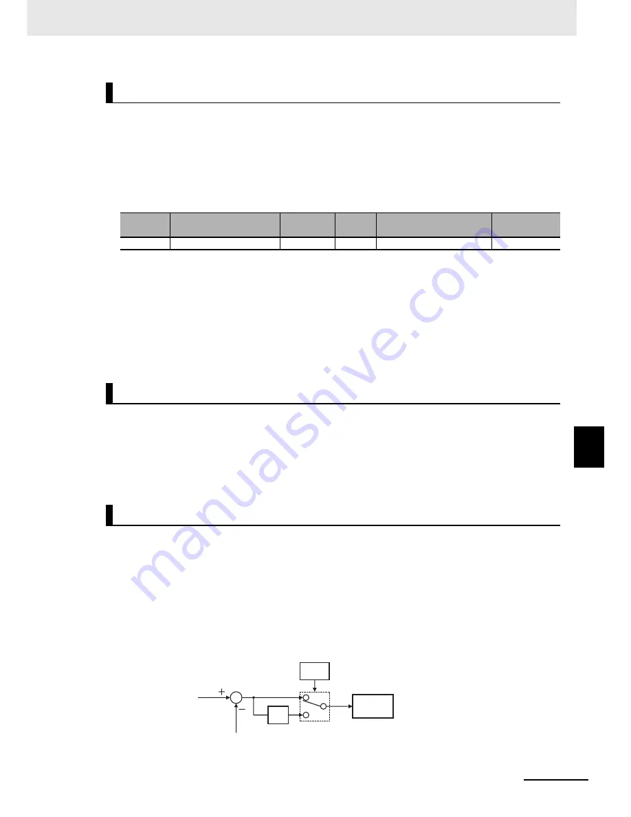
PID Deviation Reverse Output
(Example) To control a refrigerator compressor
If you are using a temperature sensor designed for use in a temperature range of 0 to
100°C at 0 to 10 V and the target and current temperatures are 5°C and 10°C, respectively,
the inverter attempts to reduce the frequency under PID control since the feedback value is
larger than the target value.
In this case, set A077 to 01. Then, the inverter attempts to increase the frequency.
A077
-1
PID feedback value
PID target value
PID
operation
(00)
(01)
Summary of Contents for SYSDRIVE MX2 SERIES
Page 1: ...Multi function Compact Inverter MX2 Series Type V1 User s Manual I585 E1 01 3G3MX2 A V1 ...
Page 32: ...CONTENTS 29 Multi function Compact Inverter 3G3MX2 V1 User s Manual I585 E1 ...
Page 108: ...2 Design 2 48 Multi function Compact Inverter 3G3MX2 V1 User s Manual I585 E1 ...
Page 176: ...4 Parameter List 4 42 Multi function Compact Inverter 3G3MX2 V1 User s Manual I585 E1 ...
Page 538: ...10 Troubleshooting 10 22 Multi function Compact Inverter 3G3MX2 V1 User s Manual I585 E1 ...
Page 598: ...12 Options 12 50 Multi function Compact Inverter 3G3MX2 V1 User s Manual I585 E1 ...
Page 614: ...Appendices A 16 Multi function Compact Inverter 3G3MX2 V1 User s Manual I585 E1 ...
Page 615: ...I 1 Multi function Compact Inverter 3G3MX2 V1 User s Manual I585 E1 I Index ...


