DRIVETRAIN COMPONENTS
Front Differential
Page 14-4
2007 Carryall 295/295 SE & XRT 1550/1550 SE Gasoline, Diesel and IntelliTach M & S Manual
14
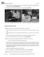
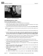
6. Secure the caliper and discs to the upright and wheel hub disc with new lock-patch bolts. Tighten the
hardware to 36 ft-lb (49 N·m)
(Figure 14-3, Page 14-2)
.
See following CAUTION.
CAUT ION
• If lock-patch bolts are not available, use Loctite 222 on new, standard thread, hex-head bolts.
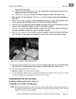
7. Secure the lower shock absorber mount to the upper A-frame with new flanged-head bolts and locknuts.
Tighten the hardware to 22 ft-lb (30 N·m).
8. Secure the top shock absorber mount to the flanged brackets on the frame with a new flanged-head bolt
and flanged locknut. Tighten the hardware to 73 ft-lb (99 N·m)
(Figure 14-2, Page 14-1)
.
9. Install the tire and wheel and finger-tighten the lug nuts.
10. Repeat steps 1 through 9 for the remaining half shaft and wheel.
11. Lift the front of the vehicle with a chain hoist or floor jack, remove the jack stands, and lower the vehicle
to the ground.
See WARNING “Lift only one end...” in General Warning, Section 1, Page 1-2.
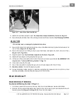
12. Use a crisscross pattern to tighten the lug nuts on both front wheels to 85 ft-lb (115 N·m).
13. Tighten both spindle locknuts to 150 ft-lb (203 N·m).
14. Adjust the front wheel camber.
See Camber Adjustment, Section 7, Page 7-12.
15. Connect the battery cables, positive (+) cable first, and tighten the hardware to 144 in-lb (16 N·m). Coat
terminals with Battery Terminal Protector Spray (CCI P/N 1014305).
FRONT DIFFERENTIAL
FRONT DIFFERENTIAL REMOVAL
See General Warning, Section 1, Page 1-1.
1. Turn the key switch OFF and remove the key. Place the Forward/Reverse handle in NEUTRAL. Chock
the wheels.
2. Disconnect the battery cables as instructed.
See WARNING “To avoid unintentionally starting...” in
General Warning, Section 1, Page 1-2.
3. Loosen the lug nuts on both front wheels.
4. Loosen the spindle nuts and lift the front of the vehicle with a chain hoist or floor jack.
See WARNING
“Lift only one end...” in General Warning, Section 1, Page 1-2.
5. Place jack stands under the lower A-frame plates and lower the vehicle onto the stands
(Figure 14-1,
Page 14-1)
.
6. Remove both half shafts.
See Half Shaft Removal on page 14-1.
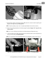
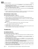
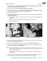
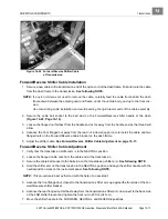
7. Remove the roll pin securing the differential pinion shaft to the front driveshaft
(Figure 14-8, Page 14-5)
.
See following NOTE.
NOTE:
Use a 1/4-inch roll pin punch to drive-out the roll pin.
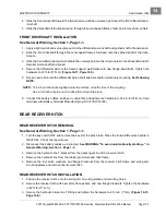
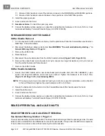
8. Remove the vent tube from the differential housing
(Figure 14-9, Page 14-5)
.
Содержание IntelliTach XRT 1550
Страница 2: ......
Страница 22: ...1...
Страница 54: ...4...
Страница 60: ...5...
Страница 90: ...6...
Страница 114: ...8...
Страница 118: ...9...
Страница 196: ...11A...
Страница 290: ...11C...
Страница 468: ...13C...
Страница 490: ...14...
Страница 498: ...15...
Страница 548: ...16...
Страница 560: ...Club Car R NOTES...
Страница 561: ...Club Car R NOTES...
Страница 562: ...Club Car R NOTES...
Страница 563: ......

