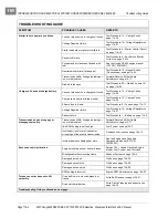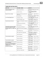
TROUBLESHOOTING AND ELECTRICAL SYSTEM: HONDA POWERED GASOLINE VEHICLES
Test Procedures
Page 11b-18
2007 Carryall 295/295 SE & XRT 1550/1550 SE Gasoline, Diesel and IntelliTach M & S Manual
11B
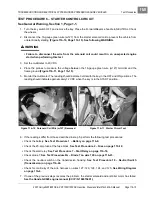
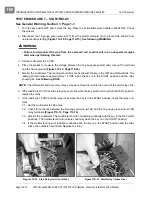
5. Monitor the multimeter. The reading should indicate 0 volts with the key in the OFF position and the For-
ward/Reverse handle in the NEUTRAL position. The reading should indicate approximately 12 VDC
when the key is in the ON position and the differential relay should click.
See following NOTE.
NOTE:
The start and accessory relays may be removed to isolate the sound of the differential relay click.
6. If the reading is 12 VDC and the relay does not click with the key switch in the ON position and the For-
ward/Reverse handle in the NEUTRAL position, replace the relay.
7. If the reading is 12 VDC and the relay clicks when the key is in the ON position, check the relay contacts.
7.1. Set the multimeter to 200 ohms.
7.2. Check for continuity between the 18-gauge gray wire (w111) and the 18-gauge purple wire (w136)
relay terminals.
7.3. Monitor the multimeter. The multimeter should indicate continuity with the key in the OFF position.
The multimeter should NOT indicate continuity when the key is in the ON position.
7.4. If the multimeter indicates continuity while the key is in the ON position and the relay clicks, the con-
tacts have failed closed. Replace the relay.
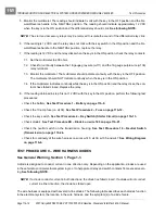
8. If the reading obtained in step 5 is not 12 VDC with the key in the ON position, perform the following test
procedures:
•
Check the battery.
See Test Procedure 1 – Battery on page 11b-9.
•
Check the 10-amp fuse (on w109).
See Test Procedure 2 – Fuse on page 11b-12.
•
Check the key switch.
See Test Procedure 4 – Key Switch (Starter Circuit) on page 11b-13.
•
Check diode 4.
See Test Procedure 9D – Diode 4 on wire 140 on page 11b-21.
•
Check the neutral switch on the transmission housing.
See Test Procedure 10 – Neutral Switch
(Transmission) on page 11b-24.
•
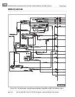
Check for continuity of the wire harness on wires w140, w139, w135, and w47.
See Wiring Diagram
on page 11b-6.
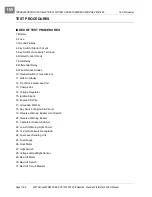
TEST PROCEDURE 9 – WIRE HARNESS DIODES
See General Warning, Section 1, Page 1-1.
A diode is designed to conduct current in one direction only. Depending on the application, diodes are used
in the vehicle to control electrical system logic, or to help protect relay and switch contacts from excessive arc-
ing.
See following NOTE.
NOTE:
If a diode conducts current in both directions, the diode has failed closed. If a diode will not conduct
current in either direction, the diode has failed open.
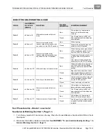
The wire harness is equipped with several in-line diodes. The following table describes each diode’s function
in the electrical system, the location in the wire harness, and the symptom(s) of a diode failure.
Содержание IntelliTach XRT 1550
Страница 2: ......
Страница 22: ...1...
Страница 54: ...4...
Страница 60: ...5...
Страница 90: ...6...
Страница 114: ...8...
Страница 118: ...9...
Страница 196: ...11A...
Страница 290: ...11C...
Страница 468: ...13C...
Страница 490: ...14...
Страница 498: ...15...
Страница 548: ...16...
Страница 560: ...Club Car R NOTES...
Страница 561: ...Club Car R NOTES...
Страница 562: ...Club Car R NOTES...
Страница 563: ......

