TROUBLESHOOTING AND ELECTRICAL SYSTEM: DIESEL VEHICLES
Test Procedures
Page 11c-34
2007 Carryall 295/295 SE & XRT 1550/1550 SE Gasoline, Diesel and IntelliTach M & S Manual
11C
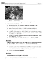
9. Connect the black (–) probe of the multimeter to the frame (ground).
10. Connect the red (+) probe of the multimeter to the 18-gauge gray wire (w140) at the bullet connector
(wire harness side).
11. The reading should indicate an over limit (no continuity). If the diode conducts current (shows continuity)
with the meter probes connected as described, the diode has failed and must be replaced.
See Wire
Harness Diode Removal, Section 12c, Page 12c-20.
12. Reverse the multimeter probes and note the reading. The multimeter should indicate approximately 540
mV, however, a range of 400-700 mV is acceptable.
13. If the readings obtained in the previous steps are incorrect, replace the diode.
See Wire Harness Diode
Removal, Section 12c, Page 12c-20.
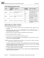
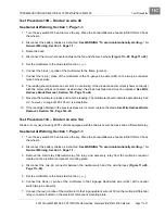
Test Procedure 13F – Diode 6 on wire 129
See General Warning, Section 1, Page 1-1.
1. Turn the key switch OFF and remove the key. Place the Forward/Reverse handle in NEUTRAL. Chock
the wheels.
2. Disconnect the battery cables as instructed.
See WARNING “To avoid unintentionally starting...” in
General Warning, Section 1, Page 1-1.
3. Disconnect the 16-gauge green wire (w127) from the starter solenoid coil
(Figure 11c-13, Page 11c-20)
.
4. Set the multimeter to the diode test function (
ç
).
5. Connect the black (–) probe to the frame (ground).
6. Connect the red (+) probe to the 16-gauge green wire (w127) at the connector.
7. The reading should indicate an over limit (no continuity). If the diode conducts current (shows continuity)
with the meter probes connected as described, the diode has failed and must be replaced.
See Wire
Harness Diode Removal, Section 12c, Page 12c-20.
8. Reverse the multimeter probes and note the reading. The multimeter should indicate approximately 540
mV, however, a range of 400-700 mV is acceptable.
9. If the readings obtained in the previous steps are incorrect, replace the diode.
See Wire Harness Diode
Removal, Section 12c, Page 12c-20.
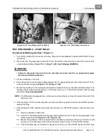
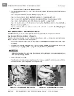
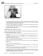
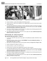
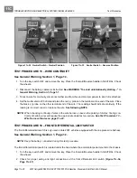
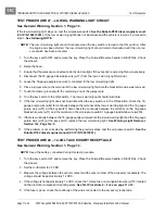
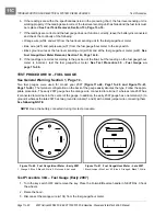
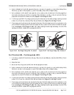
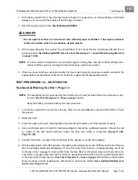
Figure 11c-29 Fuel Solenoid Three-Pin Connector
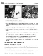
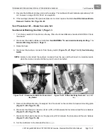
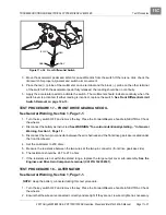
Figure 11c-30 Fuel Pump Bullet Connector
Содержание IntelliTach XRT 1550
Страница 2: ......
Страница 22: ...1...
Страница 54: ...4...
Страница 60: ...5...
Страница 90: ...6...
Страница 114: ...8...
Страница 118: ...9...
Страница 196: ...11A...
Страница 290: ...11C...
Страница 468: ...13C...
Страница 490: ...14...
Страница 498: ...15...
Страница 548: ...16...
Страница 560: ...Club Car R NOTES...
Страница 561: ...Club Car R NOTES...
Страница 562: ...Club Car R NOTES...
Страница 563: ......


