2007 Carryall 295/295 SE & XRT 1550/1550 SE Gasoline, Diesel and IntelliTach M & S Manual
Page 12c-1
12C
SECTION 12C – ELECTRICAL COMPONENTS:
DIESEL VEHICLES
ý
DANGER
• See General Warning, Section 1, Page 1-1.
ý
WARNING
• See General Warning, Section 1, Page 1-1.
STARTER AND STARTER SOLENOID
See General Warning, Section 1, Page 1-1.
Refer to the engine manual for testing, removal, disassembly, and installation procedures. See the
Kubota D722 diesel engine manual (CCI P/N 102615501).
RELAYS
See General Warning, Section 1, Page 1-1.
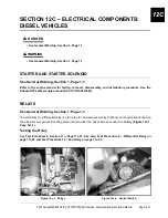
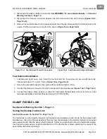
The start relay (1), differential relay (2), fan relay (3), and accessory relay (optional, not shown) are housed on
the electrical component mounting plate located under the driver-side seat near the battery
(Figure 12c-1,
Page 12c-1)
.
Testing the Relay
See Test Procedure 8, Section 11c, Page 11c-21. See also Test Procedure 9 – Differential Relay on
page 11c-22 and Test Procedure 10 – Fan Relay on page 11c-23.
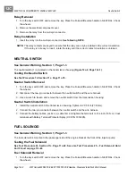
Figure 12c-1 Relays
Figure 12c-2 Neutral Switch
1
2
3
1
Содержание IntelliTach XRT 1550
Страница 2: ......
Страница 22: ...1...
Страница 54: ...4...
Страница 60: ...5...
Страница 90: ...6...
Страница 114: ...8...
Страница 118: ...9...
Страница 196: ...11A...
Страница 290: ...11C...
Страница 468: ...13C...
Страница 490: ...14...
Страница 498: ...15...
Страница 548: ...16...
Страница 560: ...Club Car R NOTES...
Страница 561: ...Club Car R NOTES...
Страница 562: ...Club Car R NOTES...
Страница 563: ......

