ELECTRICAL COMPONENTS: DIESEL VEHICLES
Oil Pressure Sensor
Page 12c-16
2007 Carryall 295/295 SE & XRT 1550/1550 SE Gasoline, Diesel and IntelliTach M & S Manual
12C
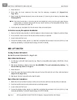
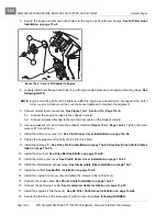
2. Insert the belt tension adjustment bolt through the belt shield mounting hole and adjustment slot and into
the alternator housing
(Figure 12c-13, Page 12c-15)
. Tighten the bolt so that it is snug, but will allow the
alternator to pivot when the belt tension is adjusted.
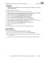
3. Place the V-belt on the alternator pulley.
4. Place a belt tension gauge on the V-belt and use a pry bar to increase the belt tension. Use a Krikit brand
belt tension gauge to measure the belt tension. The belt tension adjustment for a new belt is 45 lb and
the tension adjustment for a used belt is 30 lb.
5. Hold the pry bar to maintain the proper belt tension adjustment and tighten the belt tension adjustment
bolt to 19.0 ft-lb (25.8 N·m)
(Figure 12c-13, Page 12c-15)
.
6. Tighten the alternator mounting bolt to 19.0 ft-lb (25.8 N·m)
(Figure 12c-14, Page 12c-15)
.
See follow-
ing CAUTION.
ý
WARNING
• Remove pry bar before starting engine.
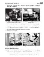
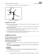
7. Connect the 12-gauge blue fusible link to the alternator
(Figure 12c-12, Page 12c-15)
. Tighten the nut
to 84 in-lb (9.5 N·m).
8. Connect the 18-gauge purple wire to the alternator
(Figure 12c-11, Page 12c-15)
.
9. Connect the battery cables, positive (+) cable first, and tighten the terminals to 144 in-lb (16 N·m). Coat
terminals with Battery Terminal Protector Spray (CCI P/N 1014305).
OIL PRESSURE SENSOR
See General Warning, Section 1, Page 1-1.
Refer to the engine manual for testing, removal, disassembly, and installation procedures. See the
Kubota D722 diesel engine manual (CCI P/N 102615501).
HEADLIGHTS
See General Warning, Section 1, Page 1-1.
Testing the Headlight Bulb and Socket
See Test Procedure 33, Section 11c, Page 11c-50. See also Test Procedure 32 – Light Switch on
page 11c-49.
Headlight Bulb Removal
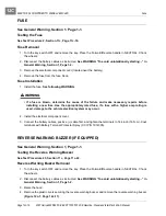
1. Turn the key switch OFF and remove the key. Place the Forward/Reverse handle in NEUTRAL. Chock
the wheels.
2. Disconnect the battery cables as instructed.
See WARNING “To avoid unintentionally starting...” in
General Warning, Section 1, Page 1-2.
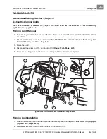
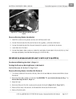
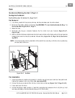
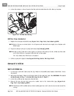
3. From the front of the vehicle, reach under the cowl and turn the connector harness/halogen bulb assem-
bly clockwise one-quarter turn
(Figure 12c-15, Page 12c-17)
.
4. Remove the connector harness/halogen bulb assembly from the headlight lens.
Содержание IntelliTach XRT 1550
Страница 2: ......
Страница 22: ...1...
Страница 54: ...4...
Страница 60: ...5...
Страница 90: ...6...
Страница 114: ...8...
Страница 118: ...9...
Страница 196: ...11A...
Страница 290: ...11C...
Страница 468: ...13C...
Страница 490: ...14...
Страница 498: ...15...
Страница 548: ...16...
Страница 560: ...Club Car R NOTES...
Страница 561: ...Club Car R NOTES...
Страница 562: ...Club Car R NOTES...
Страница 563: ......

