TROUBLESHOOTING AND ELECTRICAL SYSTEM: DIESEL VEHICLES
Test Procedures
2007 Carryall 295/295 SE & XRT 1550/1550 SE Gasoline, Diesel and IntelliTach M & S Manual
Page 11c-19
11C
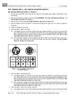
key switch in the START position, the multimeter should indicate continuity
(Figure 11c-12,
Page 11c-18)
. If the multimeter does not indicate continuity, the key switch has failed and should
be replaced.
See Key Switch Removal, Section 12c, Page 12c-7.
8.2. If the multimeter indicates continuity between the BATT and ACC terminals with the key in any posi-
tion other than START, the key switch has failed and should be replaced.
See Key Switch
Removal, Section 12c, Page 12c-7.
TEST PROCEDURE 5 – KEY SWITCH (ON POSITION)
See General Warning, Section 1, Page 1-1.
1. Turn the key switch OFF and remove the key. Place the Forward/Reverse handle in NEUTRAL. Chock
the wheels.
2. Disconnect the battery cables as instructed.
See WARNING “To avoid unintentionally starting...” in
General Warning, Section 1, Page 1-1.
3. Ensure that the key switch connector is connected correctly and is tight. If it is not, repair or replace as
necessary.
4. Remove the key switch.
See Key Switch Removal, Section 12c, Page 12c-7.
5. Set the multimeter to 200 ohms.
6. Check the BATT and IGN terminals.
6.1. Use alligator clips to connect the multimeter probes between the BATT and IGN terminals. With the
key switch in the ON position, the multimeter should indicate continuity
(Figure 11c-12,
Page 11c-18)
. If the multimeter does not indicate continuity, the key switch has failed and should
be replaced.
See Key Switch Removal, Section 12c, Page 12c-7.
6.2. If the multimeter indicates continuity between the BATT and IGN terminals with the key in any posi-
tion other than START or ON, the key switch has failed and should be replaced.
See Key Switch
Removal, Section 12c, Page 12c-7.
TEST PROCEDURE 6 – KEY SWITCH (GLOW PLUG CIRCUIT)
See General Warning, Section 1, Page 1-1.
1. Turn the key switch OFF and remove the key. Place the Forward/Reverse handle in NEUTRAL. Chock
the wheels.
2. Disconnect the battery cables as instructed.
See WARNING “To avoid unintentionally starting...” in
General Warning, Section 1, Page 1-1.
3. Ensure that the key switch connector is connected correctly and is tight. If it is not, repair or replace as
necessary.
4. Remove the key switch.
See Key Switch Removal, Section 12c, Page 12c-7.
5. Set the multimeter to 200 ohms.
6. Check the BATT and ACC terminals.
6.1. Use alligator clips to connect the multimeter probes between the BATT and ACC terminals. With the
key in the PREHEAT position, the multimeter should indicate continuity
(Figure 11c-12,
Page 11c-18)
. If the multimeter does not indicate continuity, the key switch has failed and should
be replaced.
See Key Switch Removal, Section 12c, Page 12c-7.
6.2. If the multimeter indicates continuity between the BATT and ACC terminals with the key in any posi-
tion other than PREHEAT, the key switch has failed and should be replaced.
See Key Switch
Removal, Section 12c, Page 12c-7.
Содержание IntelliTach XRT 1550
Страница 2: ......
Страница 22: ...1...
Страница 54: ...4...
Страница 60: ...5...
Страница 90: ...6...
Страница 114: ...8...
Страница 118: ...9...
Страница 196: ...11A...
Страница 290: ...11C...
Страница 468: ...13C...
Страница 490: ...14...
Страница 498: ...15...
Страница 548: ...16...
Страница 560: ...Club Car R NOTES...
Страница 561: ...Club Car R NOTES...
Страница 562: ...Club Car R NOTES...
Страница 563: ......

