KAWASAKI GASOLINE ENGINE, MUFFLER, FUEL SYSTEM, AND CLUTCHES
Fuel System
Page 13a-12
2007 Carryall 295/295 SE & XRT 1550/1550 SE Gasoline, Diesel and IntelliTach M & S Manual
13A
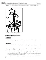
NOTE:
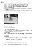
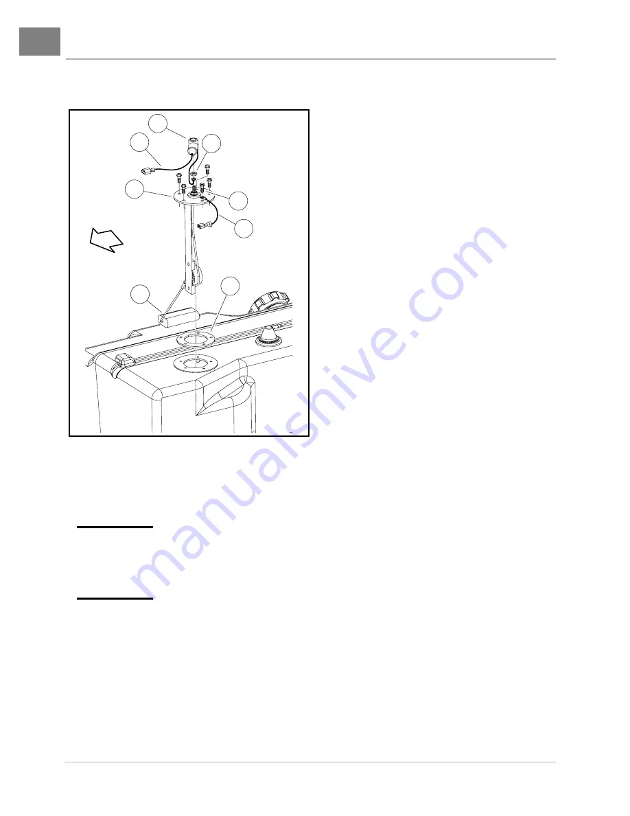
The rheostat arm and float should be positioned toward the outside surface of the fuel tank.
Fuel Level Sending Unit Installation
ý
WARNING
• Do not use electrically powered tools to remove or install the fuel level sending unit. Failure to
heed this warning could result in a fire or explosion.
ý
DANGER
• Gasoline! Flammable! Explosive! Do not smoke. Keep sparks and flames away from the
vehicle and service area.
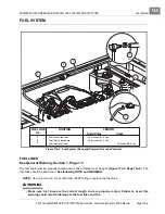
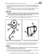
1. Place a new rubber gasket on the fuel tank with the notch (2) centered between the flange identification
mounting holes (1).
(Figure 13a-7, Page 13a-13)
.
See following NOTE.
NOTE:
The distance between the flange identification mounting holes (1) is larger than the distance
between any of the other mounting holes in the sending unit flange (5).
Ensure the replacement gasket is rubber and that the mounting holes in the gasket are aligned
properly with the mounting holes on the fuel tank.
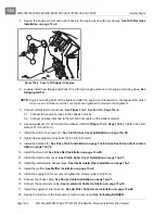
Figure 13a-6 Fuel Level Sending Unit Removal
7
5
4
8
9
3
10
6
FRONT
OF VEHICLE
Содержание IntelliTach XRT 1550
Страница 2: ......
Страница 22: ...1...
Страница 54: ...4...
Страница 60: ...5...
Страница 90: ...6...
Страница 114: ...8...
Страница 118: ...9...
Страница 196: ...11A...
Страница 290: ...11C...
Страница 468: ...13C...
Страница 490: ...14...
Страница 498: ...15...
Страница 548: ...16...
Страница 560: ...Club Car R NOTES...
Страница 561: ...Club Car R NOTES...
Страница 562: ...Club Car R NOTES...
Страница 563: ......


