CENTER SCREEN AREA / IMAGE CONTAINERS - …
LSM 710 and LSM 780
Carl Zeiss
2D View
Systems
166 M60-1-0025
e
02/2010
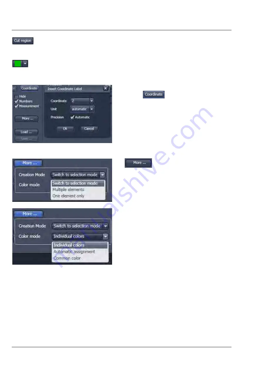
Cut Region tool: The region of a Z-Stack or 4D-image surrounded by an Overlay element
is extracted and displayed separately in a new Image Display. This function is only active if
the active Overlay element defines a closed contour or volume.
Color selection pull down: In this pull down, different colors can be assigned to the
overlay elements with a click of the mouse. A selected color is automatically assigned to
the currently selected overlay element and to all elements created afterwards.
To insert a
Coordinate Label
in the image display,
click the
button. The coordinate settings
dialog (Fig. 187) offers the available settings and
upon clicking
OK
, the selected coordinate is
displayed as a text field in the image display. This
text field is always immediately updated when the
slice/section/time point is changed in the display by
changing settings in the
Display View Option
control block or, for example, starting the
Player
animation. This feature is particularly useful to
display time or z-position in an exported animation
movie for presentations (see Fig. 186).
: The More
options (Fig. 188) allow
toggling the:
Creation of Overlay Mode
between
−
Switch to selection mode:
default setting, always switches back to the
Select
tool after creation of an overlay
element.
−
Multiple Elements:
allows to create one overly element after the
other with the selected overlay element type,
without need to re-select the respective tool.
−
One element only:
In this mode, only one element in the overlay
plane is allowed. Creating a new one deletes
the previous one.
Color Mode
between
−
Individual colors
:
The color of each element can be selected
with the color selection pull down.
−
Automatic assignment
:
The color of the overlay elements are
assigned automatically
−
Common color
:
All elements have the same color.
Fig. 187
View Options Overlay - Coordinate
Fig. 188
View Options Overlay - More


