LEFT TOOL AREA AND HARDWARE CONTROL TOOLS
LSM 710 and LSM 780
Carl Zeiss
Acquisition Tab
Systems
62 M60-1-0025
e
02/2010
5.2.5.4
Setting of Laser Line and Laser Attenuation
The
Laser
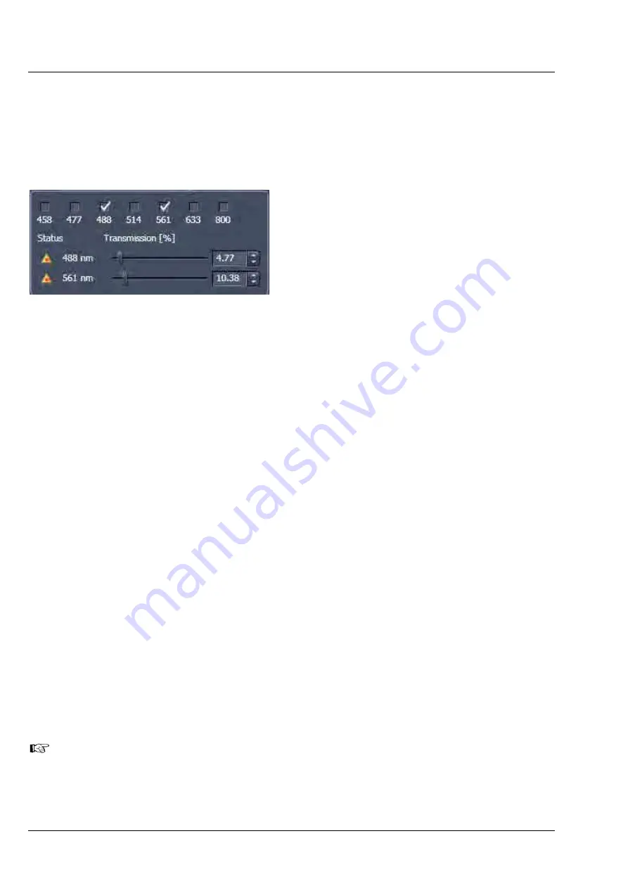
icon provides access to the control of the laser lines and their attenuation (Fig. 52). Activate a
laser line by checking the according box. This opens the attenuation slider and input box, which allows
setting the desired laser power. Make sure the laser line is indicated as active with a warning triangle. If
this is not the case, go back to the
Laser
tool and switch on the laser.
•
Use the
Transmission [%]
slider to set the
utilizable laser intensity (recommendation: start
at 5 %).
−
The transmittance of the Acousto-Optical
Tunable Filter (AOTF) changes accordingly.
This allows adapting the laser intensity very
sensitively to the job.
−
No more than 8 excitation laser lines
(wavelengths) can be active at the same
time. If more than eight laser lines are
connected to the system the Switch button is
active and the required laser lines (if not
displayed) must be allocated.
•
For this purpose, click on
Switch
and select the
required laser line that should be switched to
the one not yet displayed.
5.2.5.5
Multiple Tracks Configuration
The
sequential
imaging of
tracks
permits several tracks to be defined as one configuration for the scan
procedure, to be stored under any name, reloaded or deleted (see also section
Tool Group Setup
Manager: Imaging Setup Tool
).
The multiple tracks can either be configured manually one after the other (identical to a single track) and
then stored as recording configuration, or already existing recording configurations can be used and
changed as required.
It is also possible to load already stored track configurations (single tracks) in a recording configuration.
The set up is done using both the
Imaging Setup
tool and
Light Path
tool.
In the
Imaging Setup
tool chose
Channel Mode
as the mode for image acquisition. In the
Light Path
tool define the hardware parameters like Laser line, laser attenuation, main and secondary dichroic beam
splitters, and emission filters for the first track as described above. Ideally the parameters should be
stored as a
Track
. Add a second
Track
within the
Imaging Setup
tool. Make sure it’s selected
(highlighted) before switching to the
Light Path
tool. Again set the hardware parameters in this case for
the second track, and store them under a different name as a Track in the
Imaging Set up
tool. If more
than two tracks are requested, repeat this procedure accordingly. Finally the total combination of tracks is
stored as an imaging
Configuration
in the
Imaging Setup
tool.
When storing a configuration all the settings of the
Light Path
plus
the Gain (Master), Digital
Offset, Digital Gain and Data Depth (see section
Tool Group Online Acquisition: Channels
Tool
), the scan parameters like
Frame Size
,
Zoom, Rotation & Offset
, and
Scan Direction
parameters (see section
Tool Group Online Acquisition: Acquisition Mode Tool
) are stored.
Fig. 52
Laser line selection and attenuation


