Patching
Patching the input ports
130
RIVAGE PM10 Operation Manual
This chapter explains how to edit the input patching and output patching.
Patching the input ports
You can assign input channel patches into two groups (A and B) and switch between these groups.
This function is convenient in the following applications:
• Assigning back-up patches as group B, and switching to this group in case of emergency.
• Quickly switching between the input channel groups depending on the programs on the stage or
situations.
1.
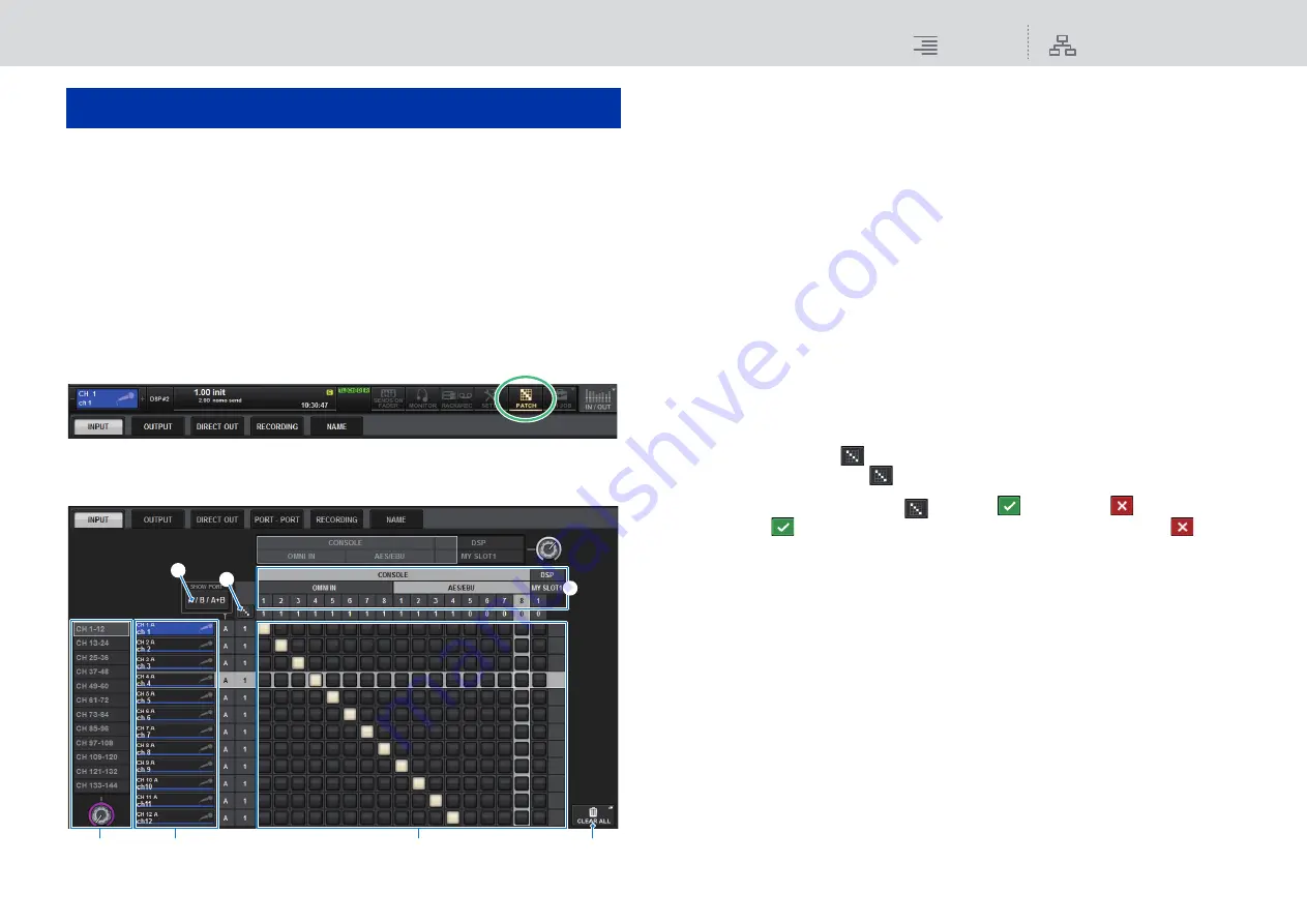
Press the PATCH button on the menu bar to access the PATCH screen.
2.
Press the INPUT tab to access the INPUT patch window.
The window contains the following items.
1
Channel list (Input channels)
Indicates the input channel numbers as patching destinations.
2
Channel display
Indicates the channels that will be assigned to the input port.
3
Grid
This grid lets you patch input ports (horizontal lines) to input channels (vertical columns).
Currently-patched grids are indicated by white squares. Press or click a desired grid to set or
disable the patch.
4
INPUT COMPONENT/SLOT/CH
This section indicates the type of the input component, slot number, and channel number for
the input port.
The abbreviations displayed in this section have the following meaning.
•
M1–M8
..........................I/O rack 1–8
•
CONSOLE
....................Control surface
•
DSP
................................DSP engine
5
SHOW PORT button
Enables you to select the ports that are displayed in the grid from A, B, and A+B.
6
Continuous patch
button
Press the continuous patch
button, and then rotate the select knob to in the upper right to
patch the intersecting channels continuously.
If you press the continuous patch
button, the
button and the
button will appear.
Press the
button again to confirm the selected continuous patches. Press the
button
to revert the continuous patches to the previous state.
7
CLEAR ALL button
Press this button to clear all patches.
3.
Use the knob in the upper right to display the desired input ports.
4.
Use the knob in the lower left corner to display the input channels.
5.
Press the desired grid cell to patch a desired channel.
NOTE
• You can patch a single input port to multiple input channels, but you cannot patch multiple input
ports to a single input channel.
• Input ports for an I/O rack that is not assigned to the TWINLANe network will not be displayed.
During off-line setting, no I/O racks will be displayed unless the DSP engine has been set as the
word clock master. If you want to patch the input ports for an I/O rack while off-line, set the DSP
engine as the word clock master temporarily to assign the I/O rack to the TWINLANe network band.
Patching
1
3
7
2
4
6
5


