Official GSK Agents in South Africa
Tel: +27 11 626 2720, [email protected]
Chapter 4 Machine Debugging methods and Modes
487
Ⅲ
Connection
1. When the adapated absolute encoder and the servo axis is linear one.
When the bus connection is normal, as well the debugging of the electric gear ratio of servo axis
or the movement direction is normal, the position from movement axis to preset value on machine tool
is regarded as the machine zero, directly set the current position on the machine as the machine
reference point by the [n axis reference point setting] soft button on the page of the “Position
-
>
Integrated coordinate”. The machine will directly position to the reference point when it returns to zero
after the reference point is set.
2. When the adapted incremental encoder or servo axis is rotation axis.
Adjust the relevant parameters based on the active level of the connection signal, zero return
type and direction applied:
BIT5 (DECI) of the bit parameter No.004: active level of deceleration signal in machine zero
return.
BIT0, BIT1, BIT2
,
BIT3
,
BIT4 (ZMX, ZMZ, ZMY
,
ZM4, ZM5) of the bit parameter No.006: X, Z,
Y, 4
th
, 5
th
axis machine zero return mode B or C selection.
BIT0, BIT1, BIT2, BIT3, BIT4 (ZCX, ZCZ, ZCY, ZC4, ZC5) of the bit parameter No.007: whether a
proximity switch is taken as both deceleration and zero signals.
BIT2(ZNLK) of the bit parameter No.011: whether the direction key in zero return is self-locked.
BIT0, BIT1, BIT2, BIT3, BIT4 (ZRSCX, ZRSCZ, ZRSCY, ZRSC4, ZRSC5) of the bit parameter
No.014: have/not the machine zero(zero turn mode BC/A)setting bit.
Data parameter No.033: low deceleration speeds of each axis in machine zero return.
Data parameter No.113: high speed of each axis in machine zero return.
BIT0, BIT1, BIT2, BIT3, BIT4 (MZRX, MZRZ, MZRY, MZR4, MZR5) of the bit parameter No.183:
each axis zero return direction: negative or positive.
Only the stroke limit switch validity is confirmed, can the machine zero return be performed.
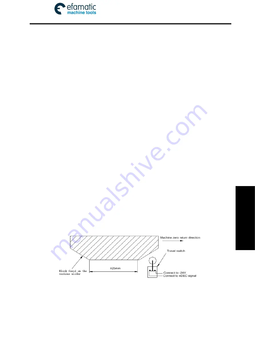
The machine zero is usually fixed at the max. travel point, and the effective stroke of the zero
return touch block should be more than 25mm to ensure a sufficient deceleration distance for
accurate zero return. The more rapid the machine zero return is, the longer the zero return touch
block should be. Or the moving carriage will rush over the block and it may affect the zero return
precision because of the insufficient deceleration distance.
The connection to AC servo motor: using a travel switch and servo motor one-turn signal
separately
Fig. 4-2
By this connection, when the deceleration switch is released in machine zero return, the one-turn
signal of encoder should be avoided to be at a critical point after the travel switch is released. In order
to improve the zero return precision, and it should ensure the motor reaches the one-turn signal of
encoder after it rotates half circle.
The parameter setting is as follows:
Bit parameter No.004 BIT5(DECI) =0
Bit parameter No.006 BIT0(ZMX) , BIT1(ZMZ) , BIT2(ZMY), BIT3(ZM4), BIT4(ZM5) =0
Bit parameter No.007 BIT0(ZCX) , BIT1(ZCZ) , BIT2(ZCY) , BIT3(ZC4), BIT4(ZC5)=0


