


Official GSK Agents in South Africa
Tel: +27 11 626 2720, [email protected]
Chapter 4 Tool Nose Radius Compensation(G41,G42)
187
Ⅰ
Programming
CHAPTER 4 TOOL NOSE RADIUS COMPENSATION (G41, G42)
4.1 Application
4.1.1 Overview
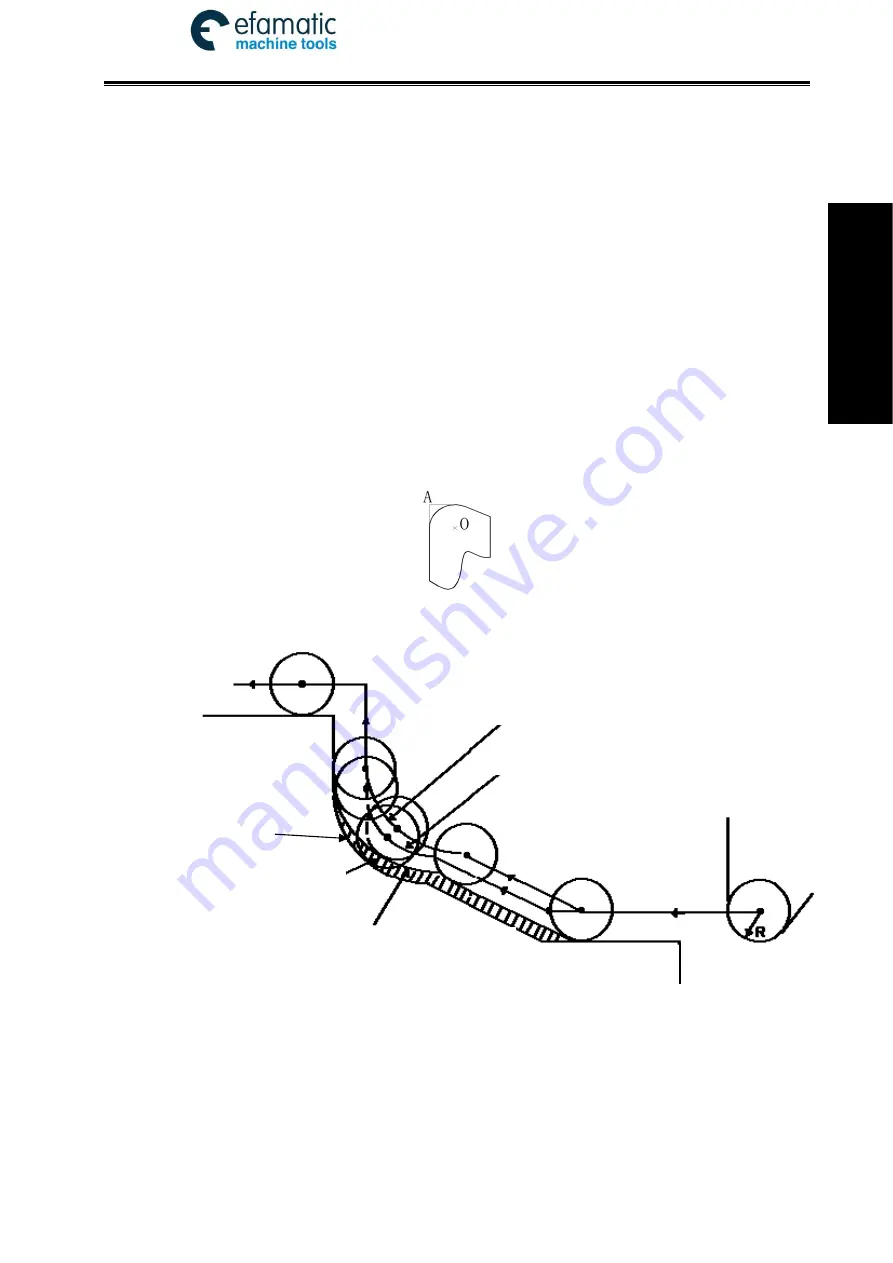
Part program is compiled generally for one point of tool according to a workpiece contour. The
point is generally regarded as the tool nose A point in an imaginary state (there is no imaginary tool
nose point in fact and the tool nose radius can be omitted when using the imaginary tool nose point to
program) or as the center point of tool nose arc ( as Fig. 4-1). Its nose of turning tool is not the
imaginary point but one arc owing to the processing and other requirement in the practical machining.
There is an error between the actual cutting point and the desired cutting point, which will cause the
over- or under-cutting affecting the part precision. So a tool nose radius compensation is needed in
machining to improve the part precision.
Fig. 4-1 Tool
Fig. 4-2 Tool nose center path
4.1.2 Imaginary Tool Nose Direction
Suppose that it is generally difficult to set the tool nose radius center on the initial position as Fig.
4-3; suppose that it is easily set the tool nose on it as Fig. 4-4; The tool nose radius can be omitted in
programming. Fig. 4-5 and Fig.4-6 correspond separately to the tool paths of tool nose center
programming and imaginary tool nose programming when tool nose radius is executed or not.
Tool path with imaginary tool nose and without C compensation
Tool path with imaginary
tool nose and C
compensation
Tool nose center path without C compensation
Tool nose center path
with C compensation
Error
Tool nose
Workpiece


