


Official GSK Agents in South Africa
Tel: +27 11 626 2720, [email protected]
Chapter 1 Programming
11
Ⅰ
Programming
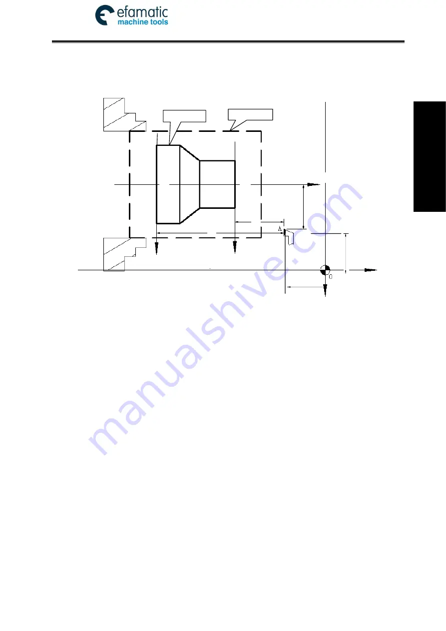
coordinate system.
The current position of workpiece coordinate system set by G50 is the program zero.
Note: Do not execute the machine reference point return without using G50 to set the workpiece coordinate
system after power on, otherwise, the alarm occurs.
In the above figure, XOZ is the coordinate system of machine tool, X
1
O
1
Z
1
is the workpiece
coordinate system of X axis located at the heading of workpiece, X
2
O
2
Z
2
is the one of X axis located
at the ending of workpiece, O point is the machine reference point, A point is the tool nose and
coordinates of A point in the above-mentioned coordinate systems is as follows:
A point in the machine tool coordinate system: (x, z);
A point in X
1
O
1
Z
1
coordinate system: (x
1
, z
1
);
A point in X
2
O
2
Z
2
coordinate system: (x
2
, z
2
).
1.3.4 Interpolation Function
Interpolation
is defined as a planar or three dimensional contour formed by path of 2 or multiple
axes moving at the same time, also called
Contour control
. The controlled moving axis is called link
axis when the interpolation is executed. The moving distance, direction and speed of it are controlled
synchronously in the course of running to form the required Composite motion path. Positioning
control is defined that motion end point of one axis or multiple axes instead of the motion path in the
course of running is controlled.
GSK980TDi X and Z axis are link axes and 2 axes link CNC system. The system possesses
linear, circular and thread interpolation function.
Linear interpolation: Composite motion path of X, Z axis is a straight line from starting point to
end point.
Circular interpolation: Composite motion path of X, Z axis is arc radius defined by R or the circle
center (I, K) from starting point to end point.
Thread interpolation: Moving distance of X or Z axis or X and Z axis is defined by rotation angle
of spindle to form spiral cutting path on the workpiece surface to realize the
Fig. 1-6
(x,z)
(x
1
,z
1
)
(x
2
,z
2
)
O
2
O
1
Z
1
(Z
2
)
X
2
X
1
z
2
z
1
x
1
/2
(x
2
/2
)
X
/2
Z
Rod
Workpiece
(0,0)
X
Z


