A. Using Modules
A-4
UniSite-xpi User Manual
Installing the PinSite Module
This section describes the various PinSite and Base installation
possibilities. Your specific configuration depends on the Base and device
package type you will be using.
Before continuing with the PinSite installation procedures, make sure you
have correctly set up your UniSite-xpi as described in the Chapter 2,
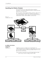
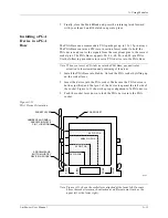
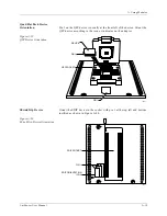
“Setup and Installation.” Figure A-2 shows the relationship between the
PinSite Module, the Bases, the MatchBooks, and the devices.
Installing the PinSite
Module in
UniSite-
xpi
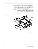
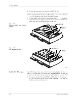
Depending on when your UniSite-xpi was manufactured, your
UniSite-xpi might have been shipped with a blank module cover installed
in place of a large module. See “Removing the Blank Module Cover” on
page 2-3 for more information.
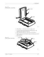
Note: You must first remove the top cover and the blank module cover, then
replace the top cover before installing the PinSite module.
Figure A-2
Installation Flow Chart
SOIC, PLCC,
or LCC Base
Matchbooks
SOIC Devices
PGA Base
PGA Device
ACTIVE
READY
PINSITE
44 Pin PLCC
44 Pin PLCC
0556-3
PLCC Devices
LCC Devices
PPI Base
PPI Adapter
Shrink DIP
Others
QFP Device
Summary of Contents for UniSite-xpi
Page 2: ...981 0014 UniSite Programming System User Manual Also Covering Legacy UniSite Programmers ...
Page 72: ...2 Setup and Installation 2 42 UniSite xpi User Manual ...
Page 134: ...3 Getting Started 3 62 UniSite xpi User Manual ...
Page 238: ...5 Computer Remote Control 5 10 UniSite xpi User Manual ...
Page 296: ...6 Translation Formats 6 58 UniSite xpi User Manual ...
Page 402: ...Keep Current Subscription Service 6 Keep Current ...


