A. Using Modules
A-14
UniSite-xpi User Manual
Using the PPI Base
The PPI interface system provides an easy exchange of programming
sockets while maintaining the electrical integrity of the programming
signals. The PPI system also allows support of devices with nonstandard
pinouts or pincounts beyond the pin driver capability of the programmer.
About the PPI Base
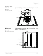
The PPI Base has 108 pins configured in four rows of 27 pins each. These
pins support up to 88 pin drivers with V
CC
and ground capability.
The PPI Base supports the following applications:
•
QFP (Quad Flat Pack)
•
Device Carriers
•
SDIP (Shrink Dip)
•
SOIC (Small Outline Integrated Circuit)
•
TSOP (Thin Small Outline Package)
•
PGA (Pin Grid Array)
•
Memory Card
•
Non-JEDEC pinout — For devices not supported in standard bases
•
Pin Driver Expansion — For devices that do not require a pin driver
on every pin to perform a programming operation.
About the PPI Adapter
A variety of PPI adapters are available from Data I/O to accommodate
the device pinouts of many package types. For example, a different PPI
adapter is available for each lead pitch (the space between adjacent pins).
The PPI Base provides a durable electrical interconnect that allows
adapters to be exchanged easily. A wide variety of sockets are available to
support the large number of device package types.
For example, an 80-pin Quad Flat Pack (QFP) is available in many
different package configurations. It is available in a square 20 x 20 pinout
or in a rectangular 16 x 24 pin package. The QFP may also have different
lead pitches and package dimensions.
Each adapter board routes universal pin drivers, V
CC
, and ground to the
appropriate device pins.
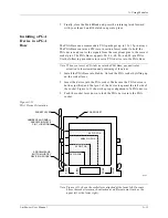
Installing a PPI
Adapter into the PPI
Base
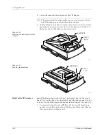
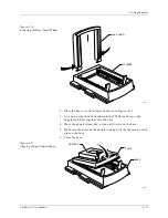
Use the following procedure to install an adapter into the PPI Base.
CAUTION: Do not touch the exposed pins or components on the base.
Contamination could lessen the programming reliability of
the adapter. Also, do not disassemble the base; doing so
could cause the pins to drop out.
Installing a device into the adapter before the adapter has
been securely placed in the base may damage the device.
1.
Make sure the PPI Base is installed in your programmer.
Summary of Contents for UniSite-xpi
Page 2: ...981 0014 UniSite Programming System User Manual Also Covering Legacy UniSite Programmers ...
Page 72: ...2 Setup and Installation 2 42 UniSite xpi User Manual ...
Page 134: ...3 Getting Started 3 62 UniSite xpi User Manual ...
Page 238: ...5 Computer Remote Control 5 10 UniSite xpi User Manual ...
Page 296: ...6 Translation Formats 6 58 UniSite xpi User Manual ...
Page 402: ...Keep Current Subscription Service 6 Keep Current ...

