A. Using Modules
UniSite-xpi User Manual
A-23
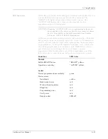
LED Indicators
SetSite has two module LEDs and eight individual socket LEDs. The two
module LEDs indicate the current status for the entire unit. The
“READY” LED lights yellow when SetSite is ready for use. The
“ACTIVE” LED lights yellow whenever an operation (such as
programming parts) is taking place.
CAUTION: When the “ACTIVE” LED is lit, programming voltages are
being applied to the device sockets. Do not remove socketed
devices from SetSite or the SetSite module from UniSite
when the “ACTIVE” LED is illuminated.
LEDs next to each socket indicate status of that socketed part. The LEDs
light green to indicate a successful operation; yellow or red indicate an
error. A red LED signals a “fatal” error, meaning that the device cannot
be programmed. A yellow LED signals a “non-fatal” error—the device
can still be programmed. (For example, a “non-blank device” error is
non-fatal because even though the device is found to contain
programmed bits, those locations can still be programmed over.) The
table below shows conditions and LED colors corresponding to each.
Condition
LED Color
Module
SetSite READY for use
“READY” yellow
Operation executing
“ACTIVE” yellow
Socket
Device programmed successfully
green
Device errors:
Non-blank
yellow
Backwards device
red
Wrong silicon signature
red
Illegal bit
red
Programming error
red
Verify error
red
Empty socket
LED off
Summary of Contents for UniSite-xpi
Page 2: ...981 0014 UniSite Programming System User Manual Also Covering Legacy UniSite Programmers ...
Page 72: ...2 Setup and Installation 2 42 UniSite xpi User Manual ...
Page 134: ...3 Getting Started 3 62 UniSite xpi User Manual ...
Page 238: ...5 Computer Remote Control 5 10 UniSite xpi User Manual ...
Page 296: ...6 Translation Formats 6 58 UniSite xpi User Manual ...
Page 402: ...Keep Current Subscription Service 6 Keep Current ...

