A. Using Modules
UniSite-xpi User Manual
A-27
Gang Programming
This example shows how to load data from a master (already
programmed) 27128 device into RAM and then gang-program that data
into a set of eight blank devices.
1.
Power up UniSite with the SetSite module installed.
2.
Using the Select device menu, select any 27128 EPROM from the
manufacturers’ and device type lists. When you have chosen a part,
UniSite will return to the Main menu.
3.
Type L to go to the Load device menu. The Load Gang/Set of Device
screen should appear. If it does not, press the PF4 key until the Load
Gang/Set screen appears. The “READY” indicator will light yellow
on SetSite’s panel when SetSite has been selected.
4.
The 27128 is a 16K x 8 part: there are 16K (or 4000 hex) addressable
locations. Therefore, the device block size should be set at 4000.
Check the device block size window and make sure that UniSite has
set the device block size to 4000 and data word width to 8.
5.
Check the User data size window. Make sure that the user data size is
set to 4000.
6.
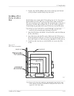
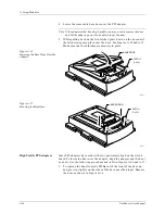
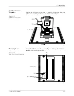
Insert the master 27128 device into SetSite’s socket number one, the
socket at the upper-left of the module. The device should be inserted
bottom-justified: no open socket pins below the device. Push the
socket lever up to the closed position.
7.
When you are certain the displayed screen parameters are correct,
push the socket lever forward again to the START position (or press
E
NTER
on the terminal keyboard) to start loading the data. The action
symbol on the UniSite screen will rotate; when the operation is
finished, a message will appear. Because the socket lever is
spring-loaded, it will automatically return to the closed position.
8.
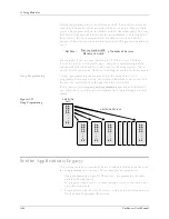
The screen will now show the data just loaded. The total set size will
be 1, meaning that the entire set of data can be programmed into one
device. A “0” appears in socket number one next to the starting
Address parameter, meaning that data was loaded from socket one
beginning at user memory address 0. Notice that asterisks appear
inside the other device socket boxes on the screen: it is not possible to
“gang-load” data into RAM with the set size equal to 1 (gang mode).
9.
Press PF2 to return to the Main menu. Open the sockets and remove
the master device. Data is now loaded into RAM. The next part of the
procedure explains how to program that data into the eight blank
devices.
10. Type P to go to the Program Gang/Set of devices menu.
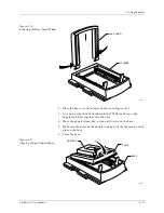
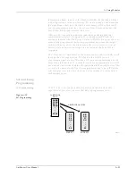
11. Insert the eight devices into the SetSite sockets. Push the socket lever
up to the closed position. Notice that starting address 0 appears in the
boxes for all eight devices on-screen. This means that UniSite will
take data from user memory address 0 to program each device, so
they will all end up with the same data.
12. Push the socket lever forward to the START position (or press E
NTER
on the terminal’s keyboard) to begin programming the devices.
Summary of Contents for UniSite-xpi
Page 2: ...981 0014 UniSite Programming System User Manual Also Covering Legacy UniSite Programmers ...
Page 72: ...2 Setup and Installation 2 42 UniSite xpi User Manual ...
Page 134: ...3 Getting Started 3 62 UniSite xpi User Manual ...
Page 238: ...5 Computer Remote Control 5 10 UniSite xpi User Manual ...
Page 296: ...6 Translation Formats 6 58 UniSite xpi User Manual ...
Page 402: ...Keep Current Subscription Service 6 Keep Current ...

