2. Setup and Installation
UniSite-xpi User Manual
2-37
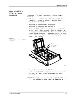
TSOP Device Orientation
There are two different pinouts for the TSOP device as shown in
Figure 2-16. The standard pinout, shown by the standard pinout ICON
on the left in Figure 2-16, shows Pin 1 indicated by a circle in the
upper-left corner of the device. The reverse pinout, shown by the reverse
pinout ICON on the right in Figure 2-16, shows Pin 1 indicated by a
triangle in the upper-left corner of the device.
1.
Press down on the outer edges of the socket.
2.
Drop the TSOP device into the socket while still holding the socket
edges down.
3.
Release the socket edges. The device should be secured.
To remove the device, press down on the socket edges and lift the device
out.
Figure 2-16
TSOP Device Orientation
1327-1
PIN 1
TSOP
SOCKET
PIN 1 OF SOCKET
DEVICE
STANDARD PINOUT ICON
REVERSE PINOUT ICON
Summary of Contents for UniSite-xpi
Page 2: ...981 0014 UniSite Programming System User Manual Also Covering Legacy UniSite Programmers ...
Page 72: ...2 Setup and Installation 2 42 UniSite xpi User Manual ...
Page 134: ...3 Getting Started 3 62 UniSite xpi User Manual ...
Page 238: ...5 Computer Remote Control 5 10 UniSite xpi User Manual ...
Page 296: ...6 Translation Formats 6 58 UniSite xpi User Manual ...
Page 402: ...Keep Current Subscription Service 6 Keep Current ...

