4. Commands
4-18
UniSite-xpi User Manual
Optional Parameter
Screens
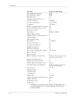
There are two types of parameter-entry screens: simple and complex.
UniSite-xpi defaults to displaying the simple, Non-default Parameters
screen. If you want to view the complex, All Parameters screen, press F4
from the Non-default Parameters screen. If you have changed any of the
default parameters, those changed parameters will also appear on the
Non-default Parameters screen.
The following parameters are found on the complex, all parameters
Program Memory Device screen.
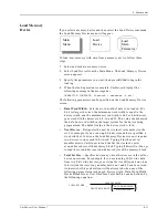
•
Memory Begin Address
—Specifies the first address, in hex, of the
first byte of data to be programmed. If the Source is RAM, it is a
beginning RAM address. If the Source is Disk, it is a beginning disk
file address. The Memory Begin Address must be an even address if
you have selected a 16-bit device. The default address is 0.
Note: (Legacy) For a SetSite operation, Memory Begin Address specifies the first
address of the device in the first socket.
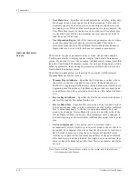
•
Device Begin Address
—Specifies the first hex device address that
will be programmed. The default is 0.
•
Device Block Size
—Specifies the size, in hex, of device data used in
device operations. At device selection, Device Block Size is set to the
device size and normally does not need to be changed. It is also
automatically set to a smaller value if the Device Begin Address is
nonzero. This parameter can be changed if desired. Entering zero sets
the Device Block Size equal to the device size.
•
Set Auto-increment
—When enabled, directs UniSite-xpi (in serial set
programming mode) to the starting memory address of the next
block in the set to be programmed. For example, if you have four
1K x 8 devices to program from a 4K x 8 block of data, using the
auto-increment option directs UniSite-xpi to point to the first address
of the next 1K block after each device has been programmed. For
single device operations, this feature should be disabled and the Next
Device parameter should be set to 1.
Note: Items with an * (asterisk) are visible on the screen only if the selected
device supports the feature.
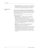
*
Illegal Bit Check
(Y,N)—Enables or disables the illegal-bit test. This
test compares data in a device against data in UniSite-xpi’s RAM to
determine if the device has already-programmed locations of
incorrect polarity. For example, UniSite-xpi returns an illegal-bit error
in the following situation: data in RAM indicates a specific bit should
be in an unprogrammed state while the corresponding bit in the
device is in a programmed state. The device cannot be programmed if
UniSite-xpi detects an illegal bit. This parameter is enabled by default.
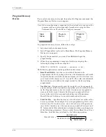
•
Blank Check
(Y,N)—Enables or disables the blank check test. A
Blank Check test checks a device for programmed bits. This
parameter defaults to Y, which enables the test.
Summary of Contents for UniSite-xpi
Page 2: ...981 0014 UniSite Programming System User Manual Also Covering Legacy UniSite Programmers ...
Page 72: ...2 Setup and Installation 2 42 UniSite xpi User Manual ...
Page 134: ...3 Getting Started 3 62 UniSite xpi User Manual ...
Page 238: ...5 Computer Remote Control 5 10 UniSite xpi User Manual ...
Page 296: ...6 Translation Formats 6 58 UniSite xpi User Manual ...
Page 402: ...Keep Current Subscription Service 6 Keep Current ...

