7. Messages
7-26
UniSite-xpi User Manual
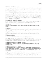
OPERATION FAILED: Incompatible user data for the device selected. Press F3.
The data in RAM is the wrong size or format for the device selected. Try the following:
- Check to make sure the JEDEC file is intended for the device you have selected.
- Confirm that you have selected the correct device.
- If both the device and JEDEC file are correct, reload the JEDEC file into RAM and attempt the
programming operation again.
- If you are using a logic device, you may need to select the “cross programming” option for this
manufacturer.
See page 7-52 for more information.
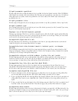
OPERATION FAILED: Incompatible vector data for the device selected.
This message will appear when you attempt an operation involving test vectors but the number of device
pins are not equal to the number of pins represented in the vectors.
OPERATION FAILED: Partial device operations not allowed. Press F3.
This message appears if you specify part of a device for a device operation. To specify the entire device,
the Device Begin Address must be 0, and the Device Block Size and User Data Size must be equal to the
size of the selected device. To set the Device Block Size and User Data Size to their default values, enter 0
in their parameter fields.
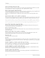
OPERATION FAILED: Preload not supported or illegal preload vector.
Device does not support preload operation or an illegal test condition is in the preload vector. Either
remove or modify preload test vector.
OPERATION FAILED: Security fuse programming error.
This message appears when the programmer cannot program the security fuse. If this message appears,
the device you are trying to program may be defective; try programming another device.
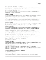
OPERATION FAILED: Structured test vector error. Press F3.
In many cases, vector failures are due to faulty devices. To determine whether this is the cause, try
programming three of the same devices. If only one device out of three has the problem, it usually means
the one device is faulty. If all three fail, then this could be related to a combination of the factors stated
below. It is also possible for a device to fail in the programmer and yet be a fully functional device.
Failures can be caused by some of the following:
- The specific characteristics of the Logic device being tested.
- The manner in which the test vectors have been written.
- The specific design of the Logic device as created by the design engineer.
- The specific defaults used by the programmer’s hardware and firmware in applying the vectors.
To determine exactly which vector/pins are failing, select the Verify option and reverify. Sometimes these
errors can be solved by using a combination of three vector “test” options: 1) High speed logic drivers, 2)
Serial vector test, and 3) Compensated vector test. These options can be enabled one at a time or in any
combination. A hardware option is also available. Refer to Application Note # 983-0372-001.
Summary of Contents for UniSite-xpi
Page 2: ...981 0014 UniSite Programming System User Manual Also Covering Legacy UniSite Programmers ...
Page 72: ...2 Setup and Installation 2 42 UniSite xpi User Manual ...
Page 134: ...3 Getting Started 3 62 UniSite xpi User Manual ...
Page 238: ...5 Computer Remote Control 5 10 UniSite xpi User Manual ...
Page 296: ...6 Translation Formats 6 58 UniSite xpi User Manual ...
Page 402: ...Keep Current Subscription Service 6 Keep Current ...


