


Boundary-Scan Architecture
B-2
ADSP-BF59x Blackfin Processor Hardware Reference
Full details of the JTAG standard can be found in the document
IEEE
Standard Test Access Port and Boundary-Scan Architecture
, ISBN
1-55937-350-4.
Boundary-Scan Architecture
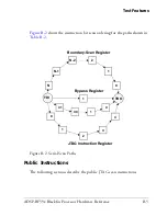
The boundary-scan test logic consists of:
• A TAP comprised of five pins (see
Table B-1
)
• A TAP controller that controls all sequencing of events through the
test registers
• An instruction register (
IR
) that interprets 5-bit instruction codes
to select the test mode that performs the desired test operation
• Several data registers defined by the JTAG standard
The TAP controller is a synchronous, 16-state, finite-state machine con-
trolled by the
TCK
and
TMS
pins. Transitions to the various states in the
diagram occur on the rising edge of
TCK
and are defined by the state of the
TMS
pin, here denoted by either a logic 1 or logic 0 state. For full details of
the operation, see the JTAG standard.
Table B-1. Test Access Port Pins
Pin Name
Input/Output
Description
TDI
Input
Test Data Input
TMS
Input
Test Mode Select
TCK
Input
Test Clock
TRST
Input
Test Reset
TDO
Output
Test Data Out
Summary of Contents for ADSP-BF59x Blackfin
Page 64: ...Development Tools 1 22 ADSP BF59x Blackfin Processor Hardware Reference...
Page 74: ...Processor Specific MMRs 2 10 ADSP BF59x Blackfin Processor Hardware Reference...
Page 244: ...Programming Examples 6 40 ADSP BF59x Blackfin Processor Hardware Reference...
Page 700: ...Programming Examples 16 78 ADSP BF59x Blackfin Processor Hardware Reference...
Page 738: ...Boundary Scan Architecture B 8 ADSP BF59x Blackfin Processor Hardware Reference...