


ADSP-BF59x Blackfin Processor Hardware Reference
11-3
UART Port Controllers
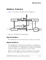
Interface Overview
Figure 11-1 on page 11-3
shows a simplified block diagram of a UART
module and how it interconnects to the Blackfin architecture and to the
outside world.
External Interface
Each UART features an RX and a TX pin. These two pins usually connect
to an external transceiver device that meets the electrical requirements of
Figure 11-1. UART Block Diagram
UART_IER
UART_THR
UART_RBR
UART_LSR
UART_LCR
UART_IIR
UART_MCR
SIC CONTROLLER
UART_DLL
UART_DLH
DMA CONTROLLER
UART_SCR
UART_GCTL
TSR
RSR
I/O POR
T
TRANSCEIVER
UART
RXREQ
TXREQ
PA
B
DA
B
ERREQ
8
8
++
BLACKFIN
RX
TX
Summary of Contents for ADSP-BF59x Blackfin
Page 64: ...Development Tools 1 22 ADSP BF59x Blackfin Processor Hardware Reference...
Page 74: ...Processor Specific MMRs 2 10 ADSP BF59x Blackfin Processor Hardware Reference...
Page 244: ...Programming Examples 6 40 ADSP BF59x Blackfin Processor Hardware Reference...
Page 700: ...Programming Examples 16 78 ADSP BF59x Blackfin Processor Hardware Reference...
Page 738: ...Boundary Scan Architecture B 8 ADSP BF59x Blackfin Processor Hardware Reference...