


Description of Operation
11-10
ADSP-BF59x Blackfin Processor Hardware Reference
transmitter itself. The processor relies on the transmitter to perform
within specification. If the transmitter violates the specification, unpre-
dictable results may occur. The 4-bit counter adds an extra level of
protection at a minimal cost. Note that because the system clock can
change across systems, the longest glitch tolerated is inversely proportional
to the system clock frequency.
The receive sampling window is determined by a counter that is clocked at
the 16× bit-time sample clock. The sampling window is re-synchronized
with each start bit by centering the sampling window around the start bit.
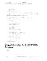
The polarity of receive data is selectable, using the
IRPOL
bit.
Figure 11-4
on page 11-10
gives examples of each polarity type.
•
IRPOL
= 0 assumes that the receive data input idles 0 and each
active 1 transition corresponds to a UART NRZ value of 0.
•
IRPOL
= 1 assumes that the receive data input idles 1 and each
active 0 transition corresponds to a UART NRZ value of 0.
Figure 11-4. IrDA Receiver Pulse Detection
0
1
16/16
PULSE
DETECT
OR
OUTPUT
SAMPLING
WINDOW
8/16
16/16
RECOVERED
NRZ INPUT
1
0
8/16
0
1
RECEIVED
IrDA
PULSE
IR POL = 1
RECEIVED
IrDA
PULSE
IR POL = 0
Summary of Contents for ADSP-BF59x Blackfin
Page 64: ...Development Tools 1 22 ADSP BF59x Blackfin Processor Hardware Reference...
Page 74: ...Processor Specific MMRs 2 10 ADSP BF59x Blackfin Processor Hardware Reference...
Page 244: ...Programming Examples 6 40 ADSP BF59x Blackfin Processor Hardware Reference...
Page 700: ...Programming Examples 16 78 ADSP BF59x Blackfin Processor Hardware Reference...
Page 738: ...Boundary Scan Architecture B 8 ADSP BF59x Blackfin Processor Hardware Reference...