


ADSP-BF59x Blackfin Processor Hardware Reference
8-17
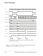
General-Purpose Timers
Figure 8-7
shows an example with three timers running with the same
period settings. When software does not alter the PWM settings at
run-time, the duty cycle is 50%. The values of the
TIMER_WIDTH
registers
control the phase between the signals.
Similarly, two timers can generate non-overlapping clocks, by cen-
ter-aligning the pulses while inverting the signal polarity for one of the
timers (see
Figure 8-8
).
Figure 8-7. Three Timers With Same Period Settings
TMR0
TMR1
TMR2
TIMER
PERIOD 1
TIMER
PERIOD 2
TIMER
PERIOD 3
TIMER
PERIOD 4
WAVEFORM
PERIOD 1
WAVEFORM
PERIOD 2
TIMER
ENABLE
ACTIVE
LOW
ACTIVE
HIGH
ACTIVE
HIGH
ACTIVE
HIGH
ACTIVE
HIGH
ACTIVE
HIGH
ACTIVE
HIGH
ACTIVE
LOW
ACTIVE
LOW
ACTIVE
LOW
ACTIVE
LOW
ACTIVE
LOW
TOGGLE_HI = 1
PULSE_HI = 1
TOGGLE_HI = 1
PULSE_HI = 1
TOGGLE_HI = 1
PULSE_HI = 1
Summary of Contents for ADSP-BF59x Blackfin
Page 64: ...Development Tools 1 22 ADSP BF59x Blackfin Processor Hardware Reference...
Page 74: ...Processor Specific MMRs 2 10 ADSP BF59x Blackfin Processor Hardware Reference...
Page 244: ...Programming Examples 6 40 ADSP BF59x Blackfin Processor Hardware Reference...
Page 700: ...Programming Examples 16 78 ADSP BF59x Blackfin Processor Hardware Reference...
Page 738: ...Boundary Scan Architecture B 8 ADSP BF59x Blackfin Processor Hardware Reference...